Attributes of ramps and stairs, moving walkways and escalators
The window Ramps & Stairs opens when a ramp, stairway, escalator or moving walkway is inserted, if automatic opening of the Edit dialog after object creation is selected (Right-click behavior and action after creating an object).
Into the window, you enter attribute values for the network object. For network objects which have already been defined, you can call the window using the following functions:
- ► In the list of network objects of the network object type, double-click the row with the desired network object.
- ► In the Network editor, select the network object of your choice. Then, on its shortcut menu, click Edit.
The network object may have additional attributes. In the network objects list of the network object type, you can show all attributes and attribute values. You can open the list via the following functions:
- ► On the network object sidebar, right-click the desired network object type. Then on the shortcut menu, click Show List (Shortcut menu in the network object sidebar).
- ► In the Network editor, select the network object of your choice. Then, on its shortcut menu, click Show In List (Selecting network objects in the Network editor and showing them in a list).
- ► On the Lists menu, in the desired category, click the network object type.
In the network objects list of the network object type, you can edit attributes and attribute values of a network object (Selecting cells in lists), (Using lists).
The objects of this object type may have relations to other objects. This is why the attributes list is shown as part of a coupled list (on the left). On the Lists toolbar, in the Relations box, you can show and edit the coupled list with the attributes of the desired relation on the right (see below Showing and editing dependent objects as relation) and (Using coupled lists).

|
Note: In lists, you can use the |

If the pedestrian should be navigated by the dynamic potential instead of the static potential when using ramps or stairways, you can select the Use dynamic potential option (Dynamic potential).
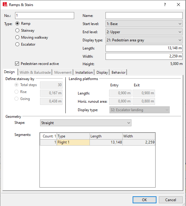
1. Make the desired changes:
| Element | Description |
|---|---|
|
No. |
Unique identification of the construction element (ramp, stairway, moving walkway or escalator) |
|
Type |
Select the desired construction element type. The functions that are irrelevant for the selected type will be enabled and displayed in gray on the tabs Installation, Design, Width & Balustrade, Movement, Display and Behavior.
You can model the length, headroom, ceiling opening and other attributes of the construction element (Modeling length, headroom and ceiling opening). You can define these attributes in the tabs Installation, Design, Width & Balustrade and Movement. |
|
Name |
Name of the construction element |
|
Start level |
Level, on which you can begin the definition of the construction element. A ramp, stairway, moving walkway or escalator can be located within a level, or the two levels Level (start) and Level (end) can be linked together. You can end the definition of a level when the construction element for the modeling of multistory buildings begins on one level and ends on another (Defining levels). |
|
End level |
Level, on which you can end the definition of the construction element. |
|
Display type |
Display type for color display of the construction element (Defining display types) |
|
Length |
Length2D: Length [m] of the construction element for the definition of the construction element in the Network Editor Length3D accounts for z-offset of the link [m]. |
|
Width |
Width of the construction element [m] |
|
Height |
Height of the construction element from the height of the level and the offset [m] |
2. Select the desired tab.
3. Make the desired changes:
Design tab
You can edit the attributes on the tab if Stairway, Escalator or Moving walkway is selected as attribute Type of the construction element.
For a stairway, the start level and end level must not be identical.
|
Element |
Description |
|---|---|
|
Define stairway by |
|
|
Landing platforms |
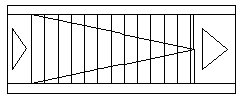
Horizontal, flat, immovable area in front of and behind the construction element:
In the wireframe view, triangles mark the landing platforms Entry and Exit preceding and following the construction element in the direction of movement:
The Horiz. Runout area is not displayed. |
|
Geometry |
|
|
Straight |
The top and bottom of the stairway are on the same line. The stairway consists of one flight of stairs and has no landing:
|
|
Straight with landing |
The top and bottom of the stairway are on the same line. It consists of two flights of stairs. The flights of stairs are connected by a flat landing:
|
|
Straight with 2 landings |
The top and bottom of the stairway are on the same line. The stairway consists of three flights of stairs. The flights of stairs are each connected by a flat landing:
|
|
Straight with 3 landings |
The top and bottom of the stairway are on the same line. The stairway consists of four flights of stairs. The flights of stairs are each connected by a flat landing:
|
|
Angle with quarter landing (90°) |
The stairway consists of two flights of stairs. They are connected by a flat landing. The bottom of the second flight of stairs is at an angle of 90° to the first flight of stairs:
|
|
U with half landing (180°) |
The stairway consists of two flights of stairs. They are connected by a flat landing. The bottom of the second flight of stairs is at an angle of 180° to the first flight of stairs:
|
|
U with 2 quarter landings (180°) |
The stairway consists of three flights of stairs. They connect two flat landings. The bottom of the third flight of stairs is at an angle of 180° to the first flight of stairs:
|


Width & Balustrade tab
Display and measurement of the handrail and the balustrade.
|
Element |
Description |
|---|---|
|
Usable width |
Width (UsableWid), pedestrians can walk on. Base for the socket width. Value range 600 to 1,200 mm. Alternatively, a warning opens at the start of the simulation. |
|
Handrail Balustrade Socket |
Width and display type of handrail (HandrWid), (HandrDisplType), balustrade (BalustrWid), (BalustrDisplType), and socket (SocketWid), (SocketDisplType). The socket width must be greater than the width of the balustrade and the handrail. Socket width = (Total width - usable width) / 2 |
|
Show balustrade (3D) |
ShowBalustr: |
 If this option is selected, the balustrade is shown in 3D mode. The balustrade does not move.
Movement tab
The movement of the construction element has an influence on the result of the simulation.
|
Element |
Description |
|---|---|
|
Treads |
|
|
Pedestrians - moving |
|
|
Pedestrians - standing |
Standing location: Side in the direction of travel, on which the pedestrians are located |
Installation tab
Area over and under the construction element.
|
Element |
Description |
|---|---|
|
Ceiling opening |
|
|
Ramp foot |
Headroom: up to the height of the headroom
|
|
Ramp foot visible |
FootVisible:
|
 If this option is not selected, the ramp foot is shown in 3D mode (not filled).
Display tab
| Element | Description |
|---|---|
|
z-offset (start) |
Start z-offset (StartZOffset): Offset > 0.000 of the Level (start) along the Z axis to the given edge for the 3D graphics mode of the construction element. This is the floor on which the pedestrians walk (A in the figure below)
|
|
z-offset (end) |
End z-offset (EndZOffset): Offset > 0.000 of the Level (end) along the Z axis to the given edge for the 3D graphics mode of the construction element.
For a Stairway or Escalator, the Z-offset (start) and Z-offset (end) must be different. The value of the z-coordinates are calculated from the height of the respective Level and the corresponding Offset. |
|
Thickness |
Thickness of the construction element for 3D representation Not relevant for the simulation. The thickness > 0 for the construction element reduces the clearance shown in 3D under the construction element because the thickness of the construction element is not considered when the length of the opening or the ramp foot of the clearance is calculated. |
Behavior tab
The following rule applies to the area behavior types: If no area behavior type is selected or no walking behavior is allocated to the area behavior type, the walking behavior allocated to the pedestrian type will be used.
You can optionally select one of the following area behavior types:
| Element | Description | |
|---|---|---|
|
Flat |
Select an area behavior type (optionally) (AreaBehavType) It is used to model occasional changes to speed or other parameters on a flat construction element, e.g. a moving walkway (Modeling area-based walking behavior) |
|
|
Downwards |
Optionally, select an area behavior type (AreaBehavType). Is used to model occasional changes to speed or other parameters on a ramp, stairway or escalator going downwards. It can be used to model the walking behavior of elderly people or wheelchair users (Modeling area-based walking behavior). |
|
|
Upwards |
Optionally, select an area behavior type (AreaBehavType). Is used to model occasional changes to speed or other parameters on a ramp, stairway or escalator going upwards. It can be used to model the walking behavior of elderly people or wheelchair users (Modeling area-based walking behavior). |
|
|
Desired speed factor |
Factor for changing the desired speed of all pedestrians on the construction element, standard value 100 %, value range 10 % to 300 %. The desired speed factor allows you to reduce the desired speed on the construction element when pedestrians move slower compared to their original desired speed, for example when the speed on a stairway is only 50% of the speed on a horizontal surface. The desired speed factor allows you to increase the desired speed on the construction element when pedestrians move faster compared their original desired speed, for example when they are moving down a ramp with a gradient. In addition to the reduced speed caused by the uphill slope, the desired speed factor will have an impact on the speed on the ramp. |
|
|
Cell size |
Edge length of a grid mesh which is used for the calculation of distances to the destination area with the static or dynamic potential (Defining global model parameters). Default value 0.15 m. Avoid values > object radius. |
|
|
Obstacle distance |
Distance up to which the nearby walls have a bearing on the distance potential (Defining global model parameters). Default 0.5 m. |
|
|
Dynamic potential |
UseDynPot: Dynamic potential attributes (Dynamic potential attributes):
|
|
Showing and editing dependent objects as relation
The attribute and attribute values of this network object type are shown in the list on the left, which consists of two coupled lists.
1. In the list on the left, click the desired entry.
The list on the right contains attributes and attribute values of network objects, and/or base data allocated to the network object selected in the list on the left (Using coupled lists):
- Pedestrians: Pedestrians within the area. The evaluation may reduce simulation speed.
- Pedestrian routes (static) (Attributes of static pedestrian routes)
- Pedestrian routes (partial) (Attributes of partial pedestrian routes)
- Walking - Pedestrian Classes
- Points: edit coordinates of the corners
The attributes are described further above.
2. On the list toolbar, in the Relations list, click the desired entry.
3. Enter the desired data.
The data is allocated.
Superordinate topic:
Modeling construction elements
Information on editing:
Importing walkable areas and obstacles from AutoCAD
Importing Building Information Model files
Defining construction elements as rectangles
Defining construction elements as polygons
Defining construction elements as circles
Editing construction elements in the Network Editor
