Importing walkable areas and obstacles from AutoCAD
You can import AutoCAD data into Viswalk. Using AutoCAD data, you can create walkable areas and obstacles for pedestrians.
With the help of maps of the area, you create the geometry required for pedestrian flow simulation.
To complete an existing network or create a new one, import polylines in the data format *.dwg and convert them.
Depending on the parameter settings you select for data import, all objects of an AutoCAD layer are converted into areas or obstacles.
- Objects of the type Line or Polyline are imported as long as they do not belong to AutoCAD blocks or AutoCAD groups.
- Lines and polylines that have a common point are connected to form a single polyline.
- Closed polylines are converted into polygons that you can import as obstacles or areas. Open polylines are not imported.
- Overlapping polygons and enclosed polygons are imported as overlapping construction elements. They are not interpreted as "holes" in areas or obstacles.
- Self-intersecting polygons are displayed in theMessages window.
- If the *.dwg file contains units for polygons, the units will be taken into consideration and the polygons will be scaled accordingly.
- In the CAD Import - Configuration window, you may select several attributes for the objects generated. For some attributes, default values are assigned.
- In Vissim, object names are derived from the concatenation of "Level <x>:" and the respective object name, where available. If there is no object name, a consecutive number is added.
|
|
Notes: In the *.dwg file, the x- and y-coordinates must be specified in meters. During import of the *.dwg file, z-coordinates are ignored. |

1. On the File menu, click > Import > CAD for Pedestrian Areas.
The Import CAD File window opens.
2. Select the *.dwg file of your choice.
3. Click the Open button.
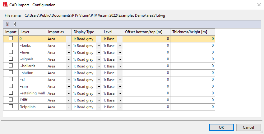
The CAD Import - Configuration window opens. A level is displayed for each row.
|
|
Notes: The unit used in the window for all lengths corresponds to the unit of length for the smallest unit of length selected, for example [m]. Check this setting before import in the menu Base Data > Network Settings > Units tab. |
4. In the columns, select the attributes of your choice.
|
Column |
Description |
|---|---|
|
Import |
|
|
Layer |
Name of the CAD level from the *.dwg file |
|
Import as |
Network object type for the level:
|
|
Display type |
Select the Display type Display types have to be defined (Defining display types). |
|
Level |
Select Level from Vissim for the CAD levels from the *.dwg file. The level has to be defined in Vissim (Defining levels). |
|
Z-Offset top/bottom |
Offset above: Positive value for the distance between the ground and the top edge of the area or the obstacle. Offset below: Negative value for the distance between the ground and the bottom edge of the area or the obstacle. |
|
Thickness/Height |
|
| Select all | In the Import column, selects all layers from the *.dwg file for import. |
| Deselect all |
Deselects all selected options in the Import column. |
 Select this option to import the respective level.
5. Confirm with OK.
The CAD Import - Configuration window closes.
The imported polygons are displayed as construction elements in the network editor and in lists. You can edit or delete the construction elements.
Superordinate topic:
Modeling construction elements
Related topics:
Attributes of ramps and stairs, moving walkways and escalators
