Defining display types
You can define display types. They specify the representation of network objects in the Vissim network, e.g. their fill style, fill color, border line style, border line color or texture. You then assign the desired display type to a network object in the Display Type attribute, e.g. the display type Road gray to a link.
In Vissim, display types are defined for road, rail, pedestrian areas, obstacles and sections, as well as for elements of escalators and elevators.
When you display network objects in the network editor, the display type settings have priority over the graphic parameter settings for network objects (List of graphic parameters for network objects).
The add-on module Viswalk allows you to show the following construction elements and specify their display type: areas, obstacles, ramps and stairs, and their display types.
|
|
Note: When you open a network file of a Vissim version that is older than Vissim 5.0, the following steps are automatically carried out:
|
1. On the Base Data menu, click > Display Types.
The Display Types list opens. Some display types can be predefined.
By default, you can edit the list (Using lists).

|
Note: In lists, you can use the |
2. In the list, on the toolbar, click the Add button  .
.
A new row with default data is inserted.
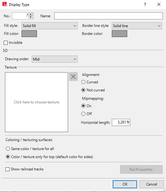
The Display Type window opens.

In the Display Type window, you enter attribute values. For display types already defined, you can open this window via the Display Types list, using the following functions:
- ► In the Display Types list, double-click the row with the desired display type.
The display type may have additional attributes. You can show all attributes and attribute values in the Display types list. You can open the list via the following functions:
- ► On the Lists menu, click > Base Data > Display Types.
- ► On the Base Data menu, click > Display Types.
You can edit attributes and attribute values in the lists (Selecting and editing data in lists).
| Element | Description |
|---|---|
|
No |
Unique number of display type |
|
Name |
Name of display type |
|
Invisible |
If vehicles and/or pedestrians are moving on the links and construction elements, they are shown. |
|
3D |
Drawing order (DrawOrder3D): Priority in drawing order in relation to other objects, that intersect at the same height. Defines if this is drawn in the foreground or in the background:
The drawing order also affects links whose display is based on the Use color scheme graphic parameter, since a display type is assigned to each link. |
|
Fill style |
|
|
Fill color |
Color between the outline of links, connectors and construction elements in the network. The graphic parameter Use display type of the network object type must be selected. The color is not accounted for in the Wireframe mode. |
|
Border line style |
|
|
Border color |
Color between outline border of links, connectors and construction elements in the network. The graphic parameter Use display type of the network object type must be selected. The color is not accounted for in the Wireframe mode. |
|
Texture |
Texture filename (TextureFilename) In the Texture box, select the desired graphic file for display of the link in 3D mode. If a texture is selected, the content of the graphic file of the texture is displayed in the TextureFilename column in the Display Types list. For textures, graphic files are available in the formats *.jpg and *.bmp. By default, they are saved to the directory ..\3DModels\Textures of your Vissim installation:
|
|
Texture horizontal length |
Scales texture to length entered. |
|
Alignment |
|
|
Anisotropic filtering |
Only as AnisoFilt column in Display types table: Make sure that in the Control Panel of your computer, in the driver settings for your graphic card, under Anisotropic filtering, you select Application-controlled or Use Application Settings. |
|
Follow link curvature |
Curved: in 3D mode:
|
|
Mipmapping |
|
|
Coloring / texturing surfaces |
|
|
Railroad tracks |
Rail: If the option is selected, on the link, tracks are displayed in 3D mode. To define the display of tracks and ties, click the Rail Properties button. |
You can also define rail properties (Defining track properties).

 If this option is selected, the display of links and construction elements is limited.
 If the option is not selected, the orientation of the texture is the same for all links, regardless of their curvature. Thus no edges are visible for overlapping links and overlapping connectors.
