Attributes of obstacles
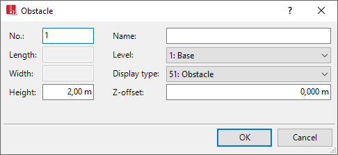
The Obstacles window opens when you insert an obstacle, if automatic opening of the Edit dialog after object creation is selected (Right-click behavior and action after creating an object).
Into the window, you enter attribute values for the network object. For network objects which have already been defined, you can call the window using the following functions:
- ► In the list of network objects of the network object type, double-click the row with the desired network object.
- ► In the Network editor, select the network object of your choice. Then, on its shortcut menu, click Edit.
The network object may have additional attributes. In the network objects list of the network object type, you can show all attributes and attribute values. You can open the list via the following functions:
- ► On the network object sidebar, right-click the desired network object type. Then on the shortcut menu, click Show List (Shortcut menu in the network object sidebar).
- ► In the Network editor, select the network object of your choice. Then, on its shortcut menu, click Show In List (Selecting network objects in the Network editor and showing them in a list).
- ► On the Lists menu, in the desired category, click the network object type.
In the network objects list of the network object type, you can edit attributes and attribute values of a network object (Selecting cells in lists), (Using lists).
The objects of this object type may have relations to other objects. This is why the attributes list is shown as part of a coupled list (on the left). On the Lists toolbar, in the Relations box, you can show and edit the coupled list with the attributes of the desired relation on the right (see below Showing and editing dependent objects as relation) and (Using coupled lists).

|
Note: In lists, you can use the |

1. Make the desired changes:
| Element | Description |
|---|---|
| No. |
Unique number of the obstacle |
| Name | Name of the obstacle |
| Level |
Level, if you want to place the obstacle on a level (Defining levels) when modeling multistory buildings. |
| z-Offset |
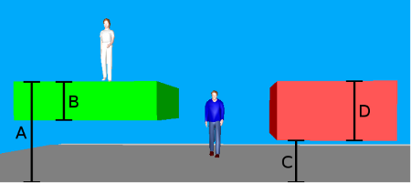
zOffsetB:Offset > 0.000 along the z-axis up to the edge specified for 3D display of the obstacle (C in the figure below) |
| Height |
Height of obstacle for 3D display(D in the figure below)
Area left (green): A = offset top, B = thickness Obstacle right (red): C = offset bottom, D = height |
| Display type |
Display type for colored display of the obstacle (Defining display types) |
|
Only for the rectangle type: |
|
| Length | Obstacle height [m] |
| Width | Obstacle width [m] |
The network object may have additional attributes, for example, the following. These can also be shown in the Attributes list:
| Long name | Short name | Description |
|---|---|---|
| Created by | CreatedBy |
Indicates whether the obstacle is user-defined or has been generated by Vissim.
|
Showing and editing dependent objects as relation
The attribute and attribute values of this network object type are shown in the list on the left, which consists of two coupled lists.
1. In the list on the left, click the desired entry.
The list on the right contains attributes and attribute values of network objects, and/or base data allocated to the network object selected in the list on the left (Using coupled lists):
2. On the list toolbar, in the Relations list, click > Points.
3. Edit the coordinates of the vertices.
The data is allocated.
Superordinate topic:
Modeling construction elements
Information on editing:
Importing walkable areas and obstacles from AutoCAD
Importing Building Information Model files
Defining construction elements as rectangles
Defining construction elements as polygons
Defining construction elements as circles
Editing construction elements in the Network Editor


