Modeling nodes
The geometry of the road network is modeled in a very detailed manner in Vissim. This exactness is not necessary for the decision of a driver for a specific path through the network. The exact traffic routing at the node is not relevant; instead, the directions on the nodes which can be turned are relevant.
In order to reduce the complexity of the network model and therefore also the calculation time and memory required, you can identify parts of the network as nodes. These positions are at the minimum the positions in which the paths merge together, or the positions which branch out in different directions. Normally these are the network sections which represent a real intersection. Do not group larger network sections, containing multiple intersections, into a node.
Nodes for evaluations, dynamic assignment and mesoscopic simulation
You define nodes for evaluations and/or dynamic assignment in the Network editor. Nodes for mesoscopic simulation can be generated for the entire Vissim network or defined individually in the Network editor.
Use the node’s attributes to define the use of the nodes: use for evaluation and/or use for dynamic assignment and/or use for mesoscopic simulation (Attributes of nodes).
Depending on the particularities of the network, a node can be used for evaluations, dynamic assignment and mesoscopic simulation. However, certain particularities of a network might require you to model additional nodes for mesoscopic simulation (Mesoscopic node-edge model).
|
|
Notes:
|

Nodes at the boundary of a network
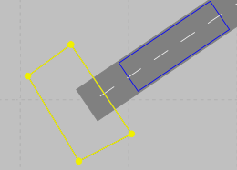
For dynamic assignment, nodes are required at the boundaries of the network where links in the Network editor begin or end. Example file ..\Examples Training\Dynamic Assignment \Detour\Detour.inpx:
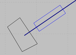
You can group nodes across several areas where links end or begin in a single node:
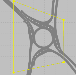
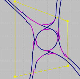
Reasonable expansion of nodes at complex intersections and roundabouts
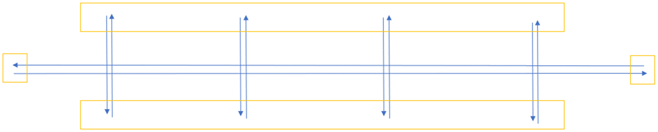
For each intersection in your Vissim network, group its crossings in a single node so that Vissim can efficiently create the dynamic assignment graph. For each of these nodes, select the attribute Use for dynamic assignment. Example: Vissim network of the section of a highway with three nodes at all three complex intersections:
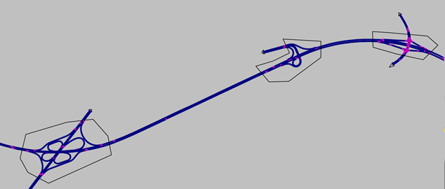
Proceed accordingly if your Vissimnetwork contains roundabouts and you want to perform a dynamic assignment: Define only one node for each roundabout. It is not necessary to define a separate node for each conflict of two movements. Example file ..\Examples Demo\Roundabout Schenectady.US\Roundabout Schenectady.inpx:
Make sure that in your Vissimnetwork a node with appropriate extension is defined for all intersections and roundabouts.
However, especially for large Vissimnetworks with many intersections and/or roundabouts, avoid grouping them all in just one node.
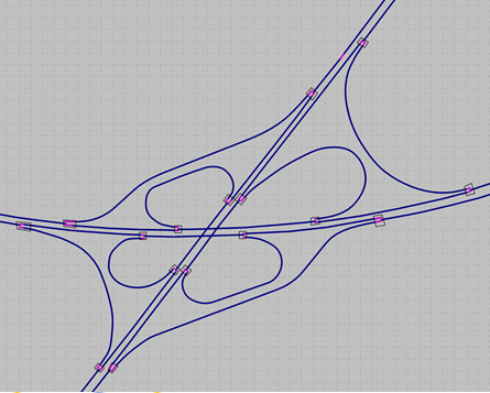
ANM import creates nodes at branching and weaving sections.
As part of the ANM import, Vissim automatically creates nodes at branching and weaving sections rather than across the entire intersection (Generated network objects from the ANM import). Sample file ..\Examples Demo\Motorway Dyn Assign Mainz.DE/Mainz - OD.inpx:
Blocking turn relations in nodes
If you typically group several crossings along a link sequence in a node for dynamic assignment and there is more than one turn relation from each node entrance to each node exit within this node, you can block the turn relations that you do not want vehicles to use. This can be useful, for example, if you want to ensure that the dynamic assignment in an interchange for the vehicles that are to travel straight ahead takes into account only the link sequence that leads straight through the interchange and not also the link sequence that leads back to the same link sequence via the ramps of the exits and entrances.
Superordinate topic:
Building an Abstract Network Graph
Information on editing:
Quick start guide Dynamic assignment
Selecting nodes, polygons or segments
Related topics:
