Attributes of nodes
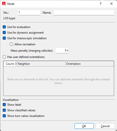
The Nodes window opens when you insert a network object and have selected to have the Edit dialog automatically opened after object creation (Right-click behavior and action after creating an object). By default, only the Nodes list is opened.
Into the window, you enter attribute values for the network object. For network objects which have already been defined, you can call the window using the following functions:
- ► In the list of network objects of the network object type, double-click the row with the desired network object.
- ► In the Network editor, select the network object of your choice. Then, on its shortcut menu, click Edit.
The network object may have additional attributes. In the network objects list of the network object type, you can show all attributes and attribute values. You can open the list via the following functions:
- ► On the network object sidebar, right-click the desired network object type. Then on the shortcut menu, click Show List (Shortcut menu in the network object sidebar).
- ► In the Network editor, select the network object of your choice. Then, on its shortcut menu, click Show In List (Selecting network objects in the Network editor and showing them in a list).
- ► On the Lists menu, in the desired category, click the network object type.
In the network objects list of the network object type, you can edit attributes and attribute values of a network object (Selecting cells in lists), (Using lists).
The objects of this object type may have relations to other objects. This is why the attributes list is shown as part of a coupled list (on the left). On the Lists toolbar, in the Relations box, you can show and edit the coupled list with the attributes of the desired relation on the right (see below Showing and editing dependent objects as relation) and (Using coupled lists).

|
Note: In lists, you can use the |

1. Make the desired changes:
| Element | Description | ||
|---|---|---|---|
|
No. |
Unique node number |
||
|
Name |
Designation of the node |
||
|
LOSType |
Level-of-service scheme type: Basis for determining the appropriate LOS scheme for result attributes LOS(All) and LOSVal(All) in node evaluation (Evaluating nodes). The LOSTyp is defined Vissim based on the node type when the simulation run is first started:
The LOSType is only calculated in the following cases:
When you edit a node or insert a new node, Vissim defines the LOSType for all nodes based on the node type the next time you start a simulation. |
||
| Showing label |
|
||
|
Dynamic assignment |
Use for dynamic assignment (UseForDynAssign):
If the nodes are not used for the dynamic assignment, deactivate the option. This saves you calculation time. |
||
|
Use for mesoscopic simulation |
UseForMeso:
|
||
|
Meso penalty (merging vehicles) |
Only when Use for mesoscopic simulation is selected: The value [s] is added to the minimum meso gap time between two consecutive vehicles on the same exit lane if they came from different entry lanes or entry links. Used to calibrate the loss of capacity at a weaving section. |
||
|
User defined orientations |
Has user defined orientations (HasUserDefOrient):
Select a direction in particular when multiple edges lead to an adjacent node and Vissim has determined an unrealistic direction. By default, in the case of multiple edges, Vissim uses the direction which occurs the most often; in the case of only two edges, it uses the direction which, in the list of available directions, occurs first (at the top, in clockwise direction). |
||
|
|||
|
Use for evaluation |
UseForEval: |
||
|
Show classified values |
Show classified values (ShowClsfValues):  Select this option to show classified values, not to show the display type selected. To show classified values, in the graphic parameters for nodes, select a color scheme and an attribute (Assigning a color to nodes based on an attribute). Select this option to show classified values, not to show the display type selected. To show classified values, in the graphic parameters for nodes, select a color scheme and an attribute (Assigning a color to nodes based on an attribute). |
||
|
Show turn value visualization |
(ShowTurnValVisual: Only active if the Use for evaluation attribute is selected, because only then can movements exist.
|
||
 If this option is not selected, the label for the respective node is hidden when label for all nodes is selected.
2. Confirm with OK.
The network object has additional attributes that you can show in the Attributes list. Among them are the following for example:
| Element | Description |
|---|---|
|
AllowRecr |
Allow recreation: only relevant, if the attribute Use for mesoscopic simulation is selected: Allows deletion and appropriate recreation of this node when running the automatic meso network node creator. Allow recreation is selected by default when a meso network node is created (Creating meso network nodes for entire Vissim network). When you change node attributes, Allow recreation is deactivated. This way your changes remain intact, when you use Create meso network nodes again and Vissim creates a meso network node. |
|
TurnValVisualSize |
Turn value visualization size: Radius [m] of the outer circle of the the turn value visualization |
|
WktPolygon |
WKT polygon: Points of the node polygon in Cartesian Vissim-world coordinates in WKT format |
|
WktPolygonWGS84 |
WKT polygon (WGS84): Points of the node polygon in WGS84 coordinates (latitude / longitude) in WKT format |
|
WktLoc |
WKT location: Absolute position of the marking position of the link in Vissim-world coordinates in WKT-POINT format |
|
WktLocWGS84 |
WKT location (WGS84): Absolute position of the marking position in WGS84 coordinates in WKT-POINT format |
|
WktWGS84Lat |
WKT WGS84 latitude: WGS84 coordinate of the latitude of the link center |
|
WktWGS84Long |
WKT WGS84 longitude: WGS84-coordinate of the longitude of the link center |
Showing and editing dependent objects as relation
The attribute and attribute values of this network object type are shown in the list on the left, which consists of two coupled lists.
1. In the list on the left, click the desired entry.
The list on the right contains attributes and attribute values of network objects, and/or base data allocated to the network object selected in the list on the left (Using coupled lists):
- Turns (evaluation): Attributes of edges in the node that are turn relations in the node-edge graph of node evaluation (Generating a node-edge graph)
- Turns (dynamic assignment): Attributes of edges in the node that are turn relations in the node-edge graph of dynamic assignment (Generating a node-edge graph)
- User defined orientations
- Movements (Evaluating nodes). To show result attributes of movements, you first need to generate the node-edge graph for evaluations (Generating a node-edge graph).
- Edges (evaluation) (Generating a node-edge graph), (Attributes of edges)
- Edges (evaluation, entering): All edges of the evaluation node that enter the node and/or end at the node
- Edges (dynamic assignment) (Generating a node-edge graph), (Attributes of edges)
- Conflict areas (Attributes of conflict areas)
- Meso turn conflicts (Attributes of meso turn conflicts)
- Meso turns (Attributes of meso turns)
- Points: edit coordinates of the corners
- Link segments: Attributes of the link segments in segment nodes
2. On the list toolbar, in the Relations list, click the desired entry.
3. Enter the desired data.
The data is allocated.
