Becoming familiar with the user interface
After you start the program, the start screen opens and the Vissim user interface with the Start page tab is displayed (Using the Start page).
Program elements of the user interface
The following figure shows the program interface with a *.inpx network file opened and individually arranged program elements:
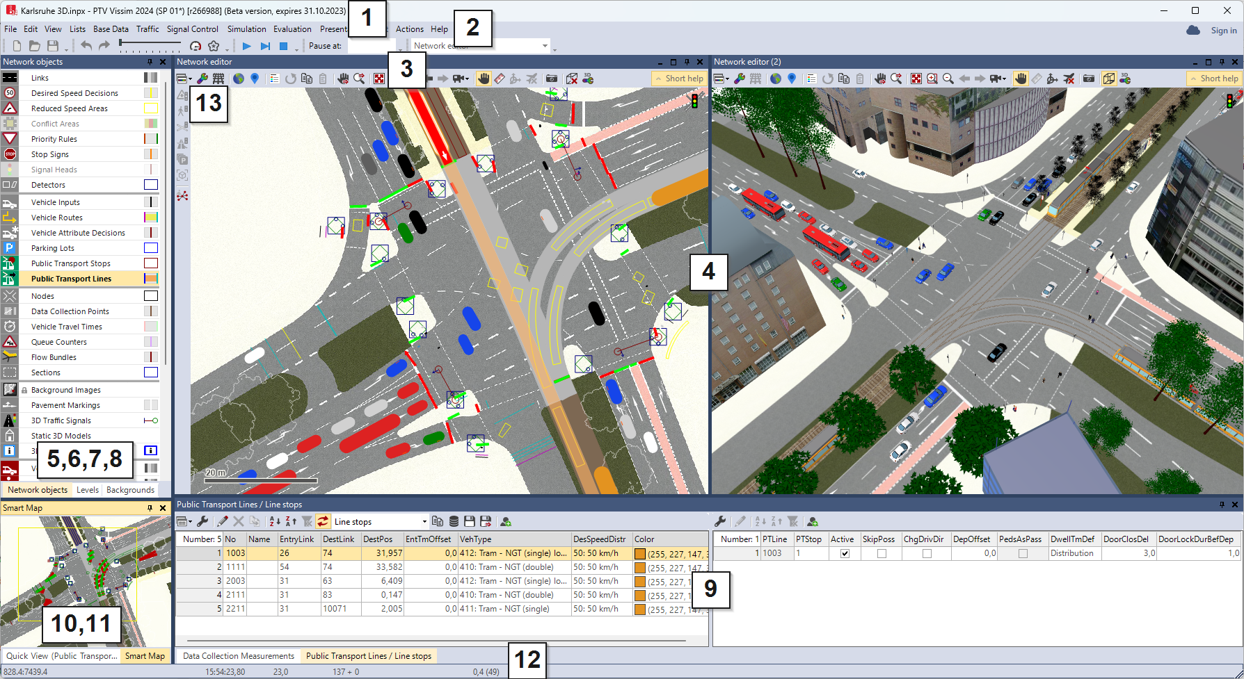
By default, the user interface contains the following elements for viewing, editing, and controlling the network, data and simulation:
|
Element |
Description |
|---|---|
|
(1) Title bar |
When an Academic license is opened, diagnostic and usage data is collected. You require an Internet connection. In the License window, in the Version section, under Product variant Academic License is displayed.
|
|
(2) Menu bar |
You can call program functions via the menus (Overview of menus). Network files used most recently in Vissim are shown in the File menu. Click on the entry if you want to open one of these network files. |
|
(3) Toolbars |
You can call program functions via the toolbars. Lists and network editors have their own toolbars (Using toolbars). |
|
(4) Network Editors |
You display the currently opened network in one or more network editors. You can edit the network graphically and customize the view in each Network Editor (Using network editors). |
|
(5) Network object sidebar |
By default, the network object sidebar, level toolbar and background image toolbar are shown on individual tabs in a window. Network object sidebar (Using the Network object sidebar):
|
|
(6) Levels toolbar |
|
|
(7) Background toolbar |
|
|
(8) Project explorer |
Displays projects, base networks, scenarios and modifications of scenario management |
|
(9) Lists |
In lists, you show and edit different data, for example, attributes of network objects. You can open multiple lists and arrange them on the screen (Using lists). |
|
(10) Quick View |
Shows attribute values of the currently marked network object. You can change attribute values of the marked network objects in the Quick View (Using the Quick View). |
|
(11) Smart Map |
Shows a small scale overview of the network. The section displayed in the Network Editor is shown in the Smart Map by a rectangle or a cross-hair. You can quickly access a specific network section via the Smart Map (Using the Smart Map). |
|
(12) Status bar |
Shows the position of the cursor in the Network Editor. Shows the current simulation second during a running simulation. |
|
(13) Vertical toolbar |
Symbols for inserting complex network objects. The vertical toolbar is located on the left edge of the network editor. |
|
Show or hide short help during insertion of complex network objects. The short help describes the necessary steps when inserting complex network objects. Images or animated GIF files in the Short help window can provide additional assistance. The short help opens automatically the first time you select a function from the vertical toolbar. |
Arranging program elements
You can arrange the program elements of the user interface according to your requirements, such as by moving, displaying from other program elements or hiding from available program elements (Changing the display of windows).
You can also arrange program elements on multiple screens. Thus you can edit the network and data in a structured way, such as by opening a network and adding more network objects, building a new network from network objects, or running a simulation.
Saving the user interface layout
The layout of the user interface is saved by default when the network is saved. The next time you open Vissim, the program elements are arranged accordingly. You can save this layout, import it and apply it to the user interface (Saving and importing a layout of the user interface).
Without a Vissim network file loaded, the Network Editor is empty.
If no network file is open, the Network Editors show an empty Vissim network (Using network editors).
Labeling mandatory fields and invalid data formats
In the following cases, Vissim highlights the input fields with a red triangle  and activates the first input field:
- Entry field is mandatory. You must enter a value or string in a valid data format.
- Part of the value or string entered is in an invalid data format. For example, for the attribute No of a link, a number must be entered. Characters are not accepted.
You must fill in all mandatory fields of a window to be able to close it with OK and make the data available in Vissim.
Point the mouse pointer at the red triangle to open a quick info about the cause of error.
Quick info displays a description
For many program elements, a small window opens temporarily, if you point the mouse pointer to the program element, e.g. a toolbar button or a network object type in the network object sidebar. The window displays a brief description of the program element.
If in an attribute list, you point the mouse pointer to an attribute name in a column header, a small window opens displaying a description of the attribute (Structure of lists).
 symbol displays information on respective program element
In some windows, the symbol is displayed next to an entry box, list box or option. If you click the symbol, a small window opens displaying information on the program element.
When you enter attribute names, Vissim suggests suitable attributes
Various functions allow you to open windows in which you can enter and select data, e.g. data of attributes or attribute values. When you enter attribute names, Vissim helps you: Once you start typing text into an input field, Vissim displays the attributes that contain the string you entered. You can adopt the suggestion made or continue with your entry:
- ► To adopt the suggestion, click the desired attribute.
The attribute is adopted into the field.
Ellipsis points mark truncated text
If the column width prevents the display of the entire text in a field, the software cuts off the text and indicates the missing text using ellipsis points: "..."
Superordinate topic:
Principles of operation of the program
Information on editing:
Program start and start screen
Starting PTV Vissim via the command prompt
Using the Network object sidebar
Shortcut menu in the network object sidebar
Using the background image toolbar
Using the 3D information sign toolbar
Selecting simple network display
Changing the display of windows
Saving and importing a layout of the user interface
