Defining 2D/3D models
You can define 2D/3D models for vehicles and pedestrians with or without 2D/3D model segments:
- Defining a 2D/3D model based on a 3D model file (Defining a 2D/3D model based on a 3D model file)
- Defining 2D/3D models without a 3D model file (Defining 2D/3D models without a 3D model file).
- You can also position 3D models of static objects, such as buildings or plants, within the network editor (Defining static 3D models).
A 3D model file is assigned to each model segment.
The 2D/3D-model can be assigned either only one model segment with a 3D model file, for example a single vehicle or multiple model segments with a 3D model file each, for example, for a train that consists of individual model files for the traction head and several goods wagons. A 2D/3D model of a pedestrian references only the first assigned model segment and its model file.
|
|
Note: When editing and saving a 3D-model file outside of Vissim that you have added in Vissim, close and re-open Vissim for the changes to take effect in Vissim. |
Defining a 2D/3D model based on a 3D model file
1. On the Base Data menu, click > 2D/3D Models.
The coupled list 2D/3D Models / 2D/3D Model Segments opens.
2. In the list on left, on the toolbar, click the Add button  .
.
A new row with default data is inserted.
The Open window opens. By default, 3D models for vehicles and pedestrians are saved to the following directories and subdirectories:
- ..\Exe\3DModels\Pedestrians: Pedestrian models, including representations of boys, girls, men, women, wheelchair users, and women with children, are available in the *.fbx format.
- ..\exe\3DModels\vehicles: Models for vehicles in various data formats:
- Rail: Segments for trams and subways in *.fbx format
- Road: Bikes, motorbikes, scooters, cars, buses and segments for buses, trucks with trailers in *.fbx format.
All files saved to the selected path are listed in the section below them. The names of the 3D models are standardized. When importing a *.inp or *.inpx network file, references to old 3D model file names are replaced automatically by the new file names. If Vissim does not find a file, a message opens.
3. Select the desired directory.
4. Double-click the desired file:
If the geometry data of the selected model does not match the default attribute data in the new row, a message is displayed. You can apply the geometry data or the default data.
The Add 2D/3D Model window opens.
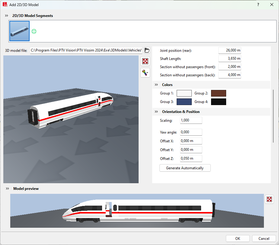
The window consists of the following sections:
- Section 2D/3D model segments: You can create a 2D/3D model from segments.
- Large Preview window: Displays the selected 2D/3D model.
- Attributes of Dimensions, Animation, Vehicle attributes, Colors, Orientation & Position: You can adjust the values.
- Section Model preview:
 symbol: Show the complete 2D/3D model created from segments. Rotating the scroll wheel changes the display:
 - Rotate down: enlarge (zoom in)
- Rotate up: reduce (zoom out)
If at the top, the 2D/3D model segments section has been expanded using the  symbol, the model is displayed in the narrow preview at the top. You can add further models to it. This allows you to create a model from segments, e.g. a train that consists of models for a power car and several railway cars. In the 2D/3D model segments section, you can change the sequence of individual 2D/3D model segments and delete 2D/3D model segments:
| Element | Description |
|---|---|
|
|
Opens or closes the 2D/3D model segments section |
|
|
Opens the Open window. You can select the file of a 2D/3D model and add it as a model segment behind the last model listed in the 2D/3D model segments section. All model segments are displayed in the 2D/3D model segments list. To show all model segments that belong to a 2D/3D model, In the 2D/3D model list, select the 2D/3D model. Then, on the list toolbar, in the Relations list box, click 2D/3D model segments (Assigning model segments to 2D/3D models). |

|
Move segment: Click the image of the model segment, hold down the mouse button and drag the image to the desired position in the sequence of the model segments. |

|
Delete segment: Point the mouse pointer to the bottom right corner and click the |

Below it, a large Preview window shows the selected 2D/3D model. If the 2D/3D model includes elements that move or change, e.g. doors or turn signals, an animation is displayed in the Preview window.
5. Make the desired settings for the attributes.
The window also provides the following commands:
| Element | Description |
|---|---|
|
3D model file |
Path and file name of the selected 2D/3D model file |
|
Large Preview window |
3D display of the selected 3D model.
|
|
|
Opens the Open window for selection of a 2D/3D model file |
|
|
Resets the Preview to default settings. Does not reset the attribute values. |
|
|
Adjust visualization: Show more elements in the preview. Supports the orientation during rotation and tilting of the 3D model in the preview:
|
|
Motion animation |
in the Preview window or during a simulation run, select and play an animation of motion states of a 2D/3D pedestrian or bike model.
|
|
|
If a model contains several motion states, for example for moving pedestrians or cyclists, these are displayed consecutively. |
|
|
Stops the animation of motion states. |
|
Vehicle attributes |
The default values of vehicle attributes depend on the model. |
|
Colors |
Colors for the different areas of the model. These are based on the colors selected for the vehicle type (Editing static data of a vehicle type):
|
|
Orientation & position |
|


 If the option is selected, the element selected is displayed in the preview.
 If this option is not selected, the element selected will not be displayed in the preview. This view corresponds to the view provided by the Network editor.

6. Confirm with OK.
The model is saved. If you have grouped the elements, the vehicle length is calculated as the sum of elements and displayed in the corresponding window of each vehicle type (Using vehicle types).
- In 2D mode, the vehicle is always displayed with the data from the 2D/3D Model Segments list (Attributes of 2D/3D model segments).
- In 3D mode, the 3D model of the selected file is used. Changes to the data in the 2D/3D Model Segments list result in the geometric data such as length or the axis positions of the preselected 3D model file in the simulation being ignored. This may result in that in the 3D visualization, vehicles overlap or seemingly hold very large distances. If the geometric data are not suitable for the model file when loading the network file *.inpx, a warning appears.
- Selection of a new 3D model overwrites all geometric data.
- If there is no reference between the 2D model and 3D model for a vehicle or pedestrian type, vehicles and pedestrians of that type are displayed in 3D mode as a colored cuboid.
- Since 3D elements have a static length, a length distribution can be defined in which you select various models with different lengths for a distribution.
- The color of a distribution, a class or a PT line is used to assign a color to the selected surfaces of the 3D model.
- During the simulation, the tractrix curves of the vehicles are used for vehicle display. Therefore, the turning behavior, in particular of the multi-part vehicles, seems more realistic; the higher simulation resolution is selected.
- 2D/3D model distributions are predefined for each vehicle type. The distribution for cars contains 7 different car models with different percentages (24 %, 16 %, 16 %, 16 %, 14 %, 20 %, 10 %). These vehicle models have been assigned as an elements relation of the 2D/3D model distribution Car. The other 2D/3D model distributions are also assigned as an elements relation.
- Changes to the model file of a standard vehicle model only affect the simulation result when the Select 3D Model window is closed with OK.
Defining 2D/3D models without a 3D model file
1. On the Base Data menu, click > 2D/3D Models.
The 2D/3D Models coupled list opens.
The attribute and attribute values of this network object type are shown in the list on the left, which consists of two coupled lists.
2. Right-click the row header.
3. On the shortcut menu, click Add Without File.
A new row with default data is inserted.

|
Note: In lists, you can use the |

In the list on the right, you can show 2D/3D model segments, assign them to a 2D/3D model, and edit attributes (Assigning model segments to 2D/3D models).
Superordinate topic:
