The building of sub-networks for Optima Micro proceed as a workflow made-up by two main high level-steps:
- Building, in PTV Visum, the PTV Optima “macro” model for the typical days.
- Building the PTV Optima Micro sub-networks based on PTV Visum “macro” model.
The step 1 is addressed by the current modeling policies.
The step 2 can be de-structured in a procedure based on 6 steps, grouped in two phases:
Building subnetworks in PTV Visum and import them in PTV Vissim
-
Creating a subnetwork in PTV Visum
Caution: Any element of the original macro model created for PTV Optima, MUST NOT BE CHANGED. This may cause incompatibilities between models and PTV Optima modules.
- ANM-export in PTV Visum.
- ANM-import in PTV Vissim.
Preparation for PTV Optima Micro
- Adjustments in PTV Vissim.
- Creation of .weg and .bew files of typical days for PTV Vissim.
- Calibration and checking plausibility of typical days in PTV Vissim.
Steps 1 to 3 are extremely helpful, but it is not strictly required that a subnetwork for PTV Optima Micro originates from a PTV Visum model.
If micro models are created independently, without Visum export, ID of nodes and their positions (including proper edges) must be consistent between macro and micro models. Additional elements (such as signal controllers, stages, signal plans, etc.) must be kept consistent as well.
Generic requirements for proper modelling in PTV Visum and PTV Vissim apply regardless.
It is important to detect the main elements that we can consider as input for the step 2.
PTV Visum model describing supply and demand
-
Nodes in PTV Visum are modelled with junction geometry data.
Complex nodes should be converted to main nodes.
Caution: Any element impacting the assignment of the original PTV Visum “macro” model, created for PTV Optima, MUST NOT BE CHANGED. Mostly this concerns nodes and main nodes, links, zones and connectors, where changes may cause incompatibilities between models and PTV Optima modules. Any adjustments must be reported back to the PTV Visum macro model.
.rim file containing demand and routes of the typical day assignment used within PTV Optima
- Typical days are e.g. working day, non-working day etc.
- Such an assignment describes demand and path choices over the 24 hours of the typical day.
The result of the process are subnetworks usable for PTV Optima Micro, associated to the typical days of the PTV Optima installation.
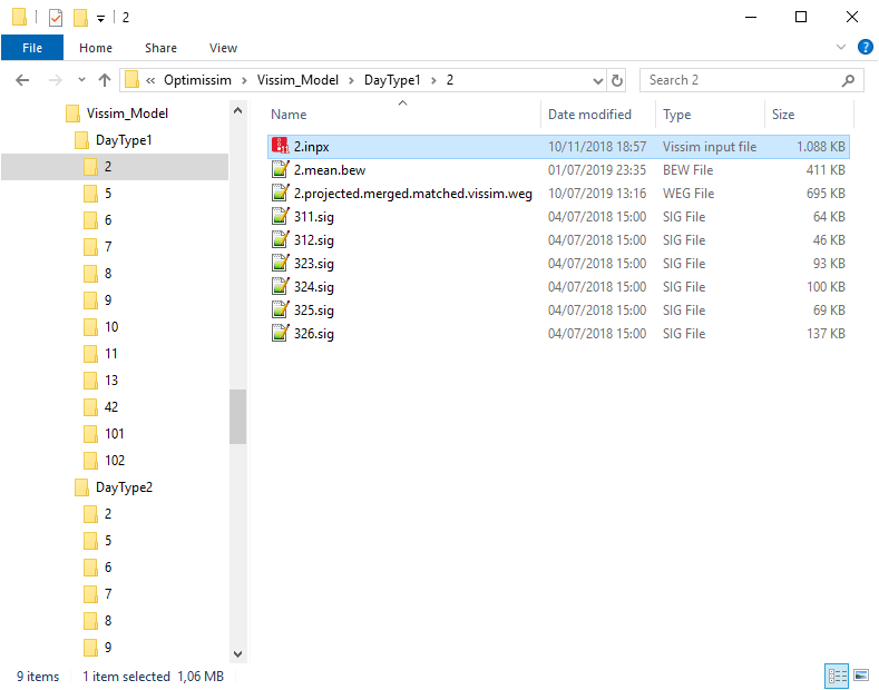
In the figure, an example of the folder structure and of the files describing a subnetwork, as detailed in the table:
| Folder/File | Description |
|---|---|
|
Vissim_Model |
The top-level folder. It is configurable and must must be deployed to all machines Optima Micro Worker (see → Optima Micro Worker (OMW)). |
|
Vissim_Model\DayTypeID |
Sub-folder of Vissim_Model. The suffix ID is numerical and must correspond to the IDs of the day types used within the PTV Optima installation. |
|
Vissim_Model\DayTypeID\ID |
Sub-folder of DayTypeID The ID is numerical and must correspond to the IDs of the subnetworks used within the PTV Optima installation. In this folder you find different files: ID.inpx: contains the PTV Vissim model. ID.mean.bew: contains a PTV Vissim .bew file produced during the offline preparation procedure (see → Provisioning of .weg and .bew files). This file describes the costs of the edges of the subnetwork over the course of the corresponding typical day. |
|
Vissim_Model\DayTypeID\ID\ID.inpx |
File contained in the folder ID. Contains the PTV Vissim model. |
|
Vissim_Model\DayTypeID\ID\ID.mean.bew |
File contained in the folder ID. Contains a file produced during the offline preparation procedure (see → Provisioning of .weg and .bew files). This file describes the costs of the edges of the subnetwork over the course of the corresponding typical day. |
|
Vissim_Model\DayTypeID\ID\ID.projected.merged.matched.vissim.weg |
File contained in the folder ID. Contains a file produced during the offline preparation procedure (see → Provisioning of .weg and .bew files). This file describes the routes through the subnetwork over the course of the corresponding typical day. |
|
Vissim_Model\DayTypeID\ID\*.* |
File contained in the folder ID. *.*: complementary files required to run the PTV Vissim model (for example, .sig files). It is possible to add arbitrary files. All files in the subfolder are part of the subnetwork and are sent around during processing. They are included in .zip file, that can be obtained by the API → Getting a micro simulation package for offline usage in PTV Vissim. For example .layx files can be added in order to specify the layout. All files are sent around, therefore a best practice is to limit the volume of additional data. Important:
|
The main architecture concepts for Optima Micro are provided in
→ How Optima works in a nutshell > OPTIMA MICRO.
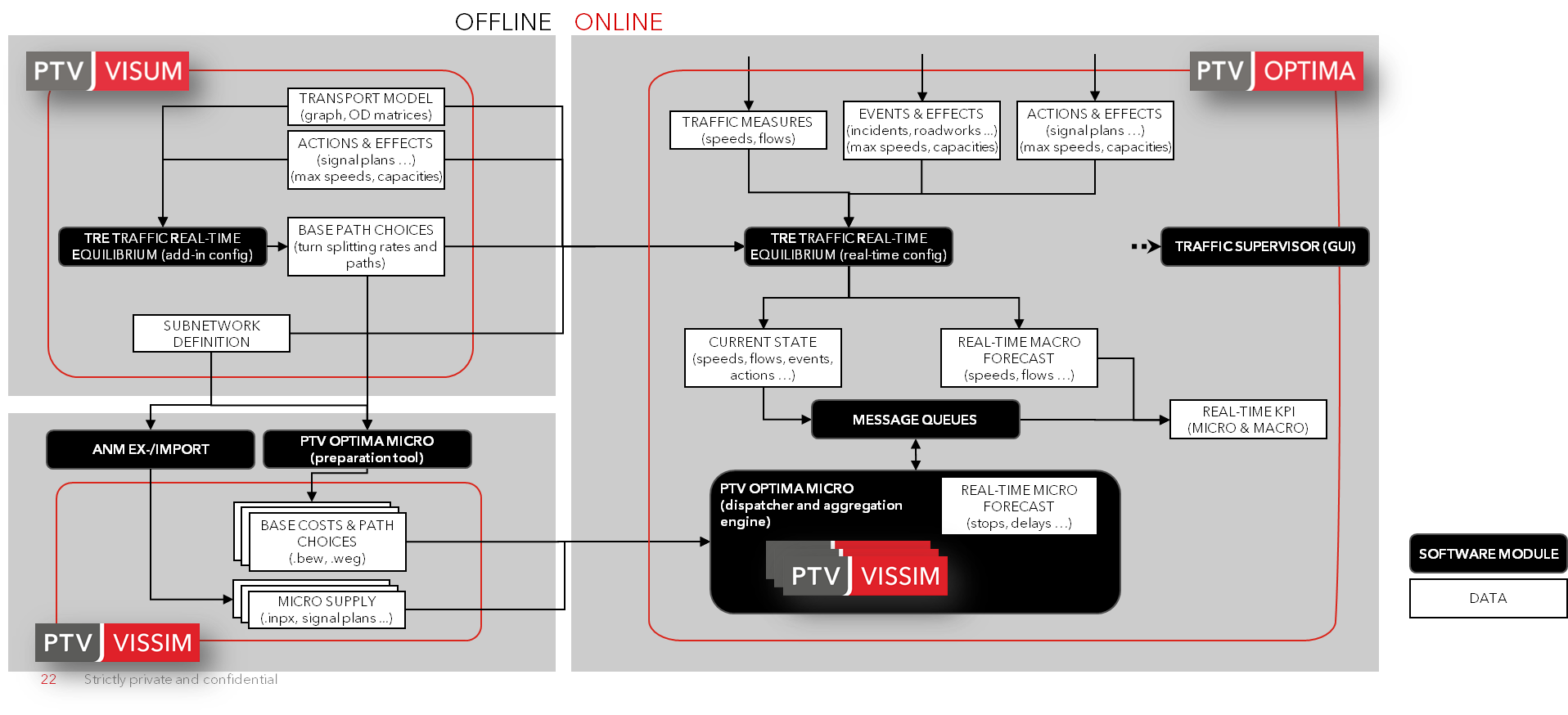
It is important highlight how the core of modeling is based on the boxes
- ANM EX-/IMPORT.
- PTV OPTIMA MICRO (preparation tool).
A good policy is to use the functionalities:
- ANM export (see → ANM export in Visum).
- ANM import (see → ANM import in Vissim).
It is not strictly required but is useful to save a lot of effort and increases the reproducibility of the process.
Most of the mapping process is based on node numbers:
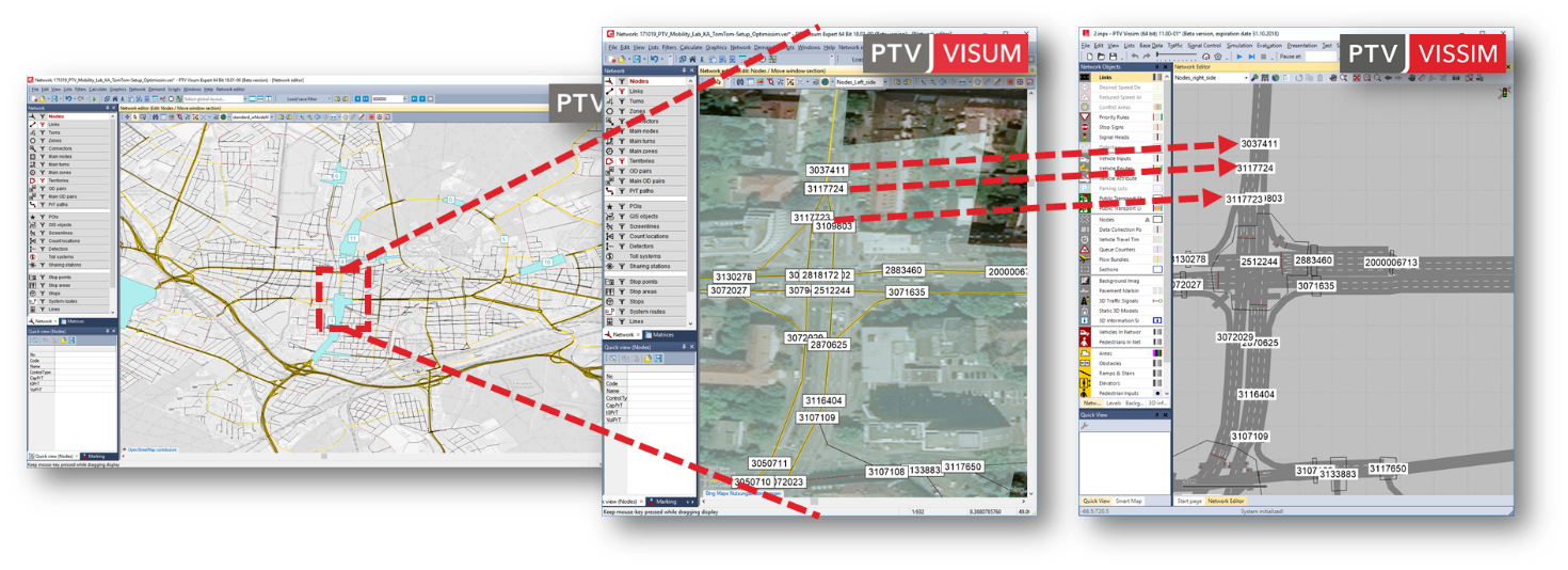
This information is maintained by the ANM export and import operations.
Node numbers must be consistent to allow proper usage and are used
- To cut the routes and demand of the offline typical day assignment
- To map current traffic states and volumes of the online environment
- To map events (speed limits, link closures, lane closures) of the online environment to the subnetworks.
Signal controller numbers and all related data (programs, stages, etc.) must be consistent.
Topics in this section