|
Note: This functionality is only available if the Junction editor and control add-on is activated ( Enabling or disabling add-ons). |
If you are in the network in the Edit mode and double-click one of the network objects nodes, main nodes, turns, or main turns, the junction editor opens. Here you can further model the network object (Fundamentals: Junction modeling).
In the junction editor and the connected signal controller editor Vissig, you can make all necessary settings for signal controllers (Signalization and The signal controller editor window Vissig).
You can edit the following network objects in the junction editor:
- Editing a node in the junction editor
- Editing a main node in the junction editor
- Editing turns in the Junction editor
- Editing main turns in the Junction editor
- Editing links in the Junction editor
- Managing signal controllers
- Managing signal groups
- Editing the geometry of a node
- Editing the signal times of a node
- Managing signal coordination groups
- Calculating and exporting ICA
- Optimizing signal cycles and split of a single signal controller
- Using turn volumes in the Junction editor
The view of the junction editor is saved with the global layout (Saving a global layout).
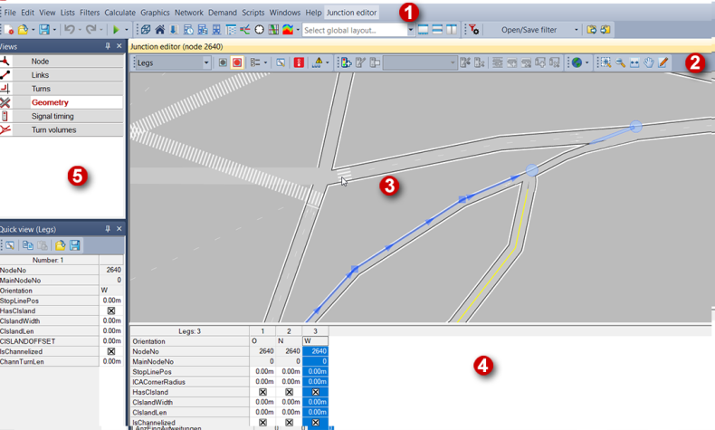
(1) Menu bar
As soon as the junction editor window is open, the menu bar displays the Junction editor menu. Among others, it contains all functionalities of the junction editor toolbar.
(2) Junction editor tool bar
The following functions, among others, are available in the toolbar. Depending on the selected view, not all symbols are available.
|
Symbol |
Name |
Description |
|
Selected network object type |
Selection of the displayed network object Tip Alternatively, you can change the network object type using the shortcut menu of selected objects. |
|
|
No synchronization with other windows |
The junction editor is not synchronized with other windows. |
|
|
Synchronization with other windows: Highlight |
The junction editor is synchronized with other windows. |

|
Synchronization with other windows: Highlight and move view |
Network objects marked in the junction editor are also marked in other windows and vice versa. If required, the network section is shifted so that all highlighted objects are visible. |

|
Synchronization with other windows: Highlight with autozoom |
Network objects marked in the junction editor are also marked in other windows and vice versa. In addition, an autozoom is triggered on the marked object(s). |

|
Show only selected node |
Display and editing can be restricted to the selected (main) node in the Geometry view using this symbol. |

|
Settings for current view |
You can use the symbol to define special settings for the respective view. |
|
|
Select attributes |
Selection of the attributes which are displayed in the list view of the junction editor. |
|
|
Vissim node preview |
Opens the Vissim export preview. It shows the selected node and the adjacent nodes. |

|
Check ICA computability |
Using the triangle next to the symbol, you can, among other things, calculate ICA for selected nodes (Calculating and exporting ICA). |
|
|
Create signal controller |
Use the symbol to create a signal controller. Note The signal controller will automatically be allocated to the currently displayed node/main node if the Signalized control type has been selected. |
|
|
Edit signal controller |
Use the symbol to edit a signal controller. |

|
Switch on/off signal controller |
You can activate and deactivate a signal controller using this symbol. |

|
Switch signal program |
Use the symbol to select the desired signal program. |
|
|
Edit signal program data |
|
|
|
Delete signal controller |
Use the symbol to delete a signal controller. |
|
|
Create signal group |
Use the icon to create a signal group. |
|
|
Delete signal group |
Use the symbol to delete a signal group. |
|
|
Use stage templates |
You can use the symbol to apply existing stage templates to generate stages in the Signal timing view . |
|
|
Create stage |
Use the symbol to create a stage. |
|
|
Delete stage |
Use the symbol to delete a stage. |

|
Enable/disable background map |
Use the symbol to activate a background map (Displaying background maps in the Junction editor). |

|
Edit graphic parameters |
Use the symbol to open the Edit graphic parameters window. |

|
Opacity of the network display |
Use the slider to adjust the opacity of the display. |


(3) Schematic view of the selected object
The schematic view displays the currently selected object.
You can change the section displayed in the junction editor window. Similar functionalities as those in the Network editor window are provided for this(Network editor window).
(4) List view of the selected object
The list view shows the attributes of the selected object. You can edit the attribute values of editable attributes right in the list.
|
Notes: You can select a font for the list view and specify, whether the Short name or the Long name of the attributes shall be displayed in the list view (Adjusting the display and the input options of the list view). The Signal timing view does not show attributes below the node but the signal times of the node, which you can edit (Editing the signal times of a node). |
(5) The Views window
Here you can select an object type. If you switch to another object type in the Views window, the schematic view and the list view will display the new object. The following views are provided:
- Nodes
- Main nodes
- Links
- Turns
- Main turns
- Geometry
- Signal timing
- Turn volumes
