Attributes of connectors
The Connectors window opens when you insert a network object and have selected to have the Edit dialog automatically opened after object creation (Right-click behavior and action after creating an object). By default, only the Connectors list is opened.
Into the window, you enter attribute values for the network object. For network objects which have already been defined, you can call the window using the following functions:
- ► In the list of network objects of the network object type, double-click the row with the desired network object.
- ► In the Network editor, select the network object of your choice. Then, on its shortcut menu, click Edit.
The network object may have additional attributes. In the network objects list of the network object type, you can show all attributes and attribute values. You can open the list via the following functions:
- ► On the network object sidebar, right-click the desired network object type. Then on the shortcut menu, click Show List (Shortcut menu in the network object sidebar).
- ► In the Network editor, select the network object of your choice. Then, on its shortcut menu, click Show In List (Selecting network objects in the Network editor and showing them in a list).
- ► On the Lists menu, in the desired category, click the network object type.
In the network objects list of the network object type, you can edit attributes and attribute values of a network object (Selecting cells in lists), (Using lists).
The objects of this object type may have relations to other objects. This is why the attributes list is shown as part of a coupled list (on the left). On the Lists toolbar, in the Relations box, you can show and edit the coupled list with the attributes of the desired relation on the right (see below Showing and editing dependent objects as relation) and (Using coupled lists).

|
Note: In lists, you can use the |

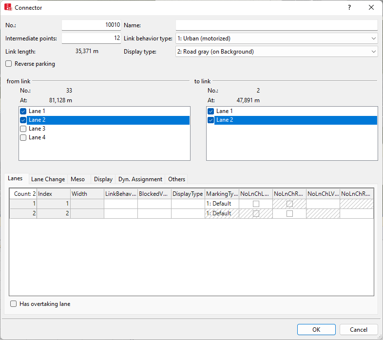
Basic attributes of connectors
The basic attributes of the network element are shown in the upper area of the window and in the list of network objects for the particular network object type.
| Element | Description |
|---|---|
|
No. |
Unique number of the connector |
|
Name |
Name of the connector |
|
Intermediate points |
Number of intermediate points between start point and end point for true position modeling. Intermediate points are not relevant for the driving behavior of vehicles driving on them. If you enter more intermediate points, you can model the connector more precisely. For straight connectors, start point and end point are sufficient. Up to 15 points may be useful for longer connectors, for example, for turns. When you e.g. move the start or end point of a connector to a different link or another lane, the intermediate points and the course of the connector are recalculated. You can edit intermediate points, for example by using z-Offset for each intermediate point, or attributes referring to the radius (Defining altitude of link intermediate points using z-offset), (Editing points in links or connectors). |
|
BehaviorType |
Link behavior type (LinkBehavType): Standard driving behavior of the vehicles for this link, if no individual link behaviour type is allocated to the lanes of this link. Vehicles using a lane, that a link behavior type has been allocated to, take the link behavior type of this lane into account (Defining link behavior types for links and connectors), (Defining driving behavior in a driving behavior parameter set). |
|
Link Length |
|
|
Display type |
Colored display of the connector (Defining display types) |
|
from link to link |
Lanes of the exit link (FromLink) to lanes of the next link (ToLink) between which the connector is inserted. Always select the same number of lanes in both lists. This assignment can also be subsequently edited. |
Lanes tab
The list in the tab contains, amongst others, the following attributes:
| Column | Description |
|---|---|
|
Index |
Unique number of the lane. You cannot change this entry later on. |
|
Width |
Width of the lane If several lanes are defined, several rows are displayed. You can define different widths. The width has an effect on:
|
|
BehaviorType |
Link behavior type (LinkBehavType: lane-specific link behavior type that differs from the standard link behavior type of the connector |
|
BlockedVehClasses |
Blocked vehicle classes on this lane.
|
|
Display type |
Color of lane (Defining display types) |
|
NoLnChLAllVehTypes NoLnChRAllVehTypes |
No lane change left – all vehicle types and No lane change right– all vehicle types: |
|
NoLnChLVehClasses NoLnChRVehClasses |
No lane change left - vehicle classes and No lane change right - vehicle classes: Vehicle classes, whose vehicles must not change from a chosen lane to the adjacent lane in the direction of travel. A prohibition of lane changes is shown in the 2D and 3D mode by means of a solid line. |
Has overtaking lane (HasOvtLn): The inner lane may only be used for overtaking maneuvers on the oncoming lane. This is only possible on links with at least two lanes (Modeling overtaking maneuvers on the lane of oncoming traffic).
 If this option is selected, for right hand traffic, the outer left lane is displayed as the passing lane, with hatched background. For left hand traffic, the lane on the far right is the passing lane, displayed with hatched background.
If a passing lane and regular lane of a link of the opposite direction overlap for long enough, the overlapping area may be used for passing.
Only select this attribute for links on which passing is actually allowed in reality. Avoid passing lanes on which overtaking is not possible in reality, e.g. at intersections or in traffic controlled areas.
You can also select this attribute for several, successive links that are connected via connectors and have at least two lanes. Vehicles can then use the entire overlapping area for overtaking maneuvers.
If the passing lane is closed for a vehicle class, the vehicles of this class cannot use the passing lane for overtaking.
You can place other network objects, e.g. data collection points, on passing lanes.
Passing lanes are not shown in 3D mode.
|
|
Notes:
The option All Vehicle Types is a virtual vehicle class that automatically includes all new vehicle types and vehicle types that have not been assigned a vehicle class yet. |
Lane Change tab
The tab contains, amongst others, the following attributes:
| Element | Description | ||
|---|---|---|---|
|
Desired Direction |
Direction (Direction): Displays directional indicators on the vehicle during a simulation run when the vehicle follows a vehicle route along this connector:
Vehicles without a desired direction and vehicle route always drive on the next connector with the criterion All. If no such connector exists at the end of the link, these vehicles are removed from the Vissim network. The desired direction is displayed in the following order of priority: 1. Current lane change 2. Desired lane change 3. Desired direction of current link 4. Desired direction of the next connector of the route which has the desired direction right or left, if the vehicle is within the attribute value of the Lane change distance, whose value results from the input field Fixed value or the Distribution. If the vehicle wants to reach a parking space and this connector leads to the parking space, the vehicle flashes 10.0 m before reaching the connector. 5. Turn signal direction set via external driver model in the DriverModel.DLL file (Activating external driver model via Driver Model DLL file) The vehicle will not flash when traveling upstream of the connector to a stop or parking lot and stopping therein, even if they are within the lane change distance. In these cases, the vehicle does not flash until it starts again in the stop or parking lot to reach the connector on its vehicle route. In the case of a public transport vehicle, the Door lock duration before departure must be completed. If the public transport vehicle leaves out the stop, it can start flashing from a distance of 50 m upstream of this stop. Effect of the Direction attribute when searching for the turning point after backing out of a parking lot and for reverse parking: For backing out of a parking lot, upstream connectors are taken into account only, which lead from the parking lot link to the link on which the vehicle wishes to continue its journey and which are not assigned the direction request None. Connectors leading to the parking lot are ignored. Connectors leading to the parking lot or for which the Reverse parking attribute is selected are ignored. For reverse parking, downstream connectors are taken into account only, which lead from the parking lot link to the link on which the vehicle wishes to continue its journey and which are not assigned the direction request All. Connectors leading to the parking lot or for which the Reverse parking attribute is selected are ignored. |
||
|
Emergency stop distance |
EmergStopDist: Is used to model the lane change rule of vehicles that follow their route, or in dynamic assignment their path, default value = minimum length = 5 m. If these lanes could not be reached before the connector at the Emergency Stop position, the vehicle stops and waits for a sufficiently large gap. The system measures upstream starting from the beginning of the connector. If a vehicle has to make more than one lane change, 5 m per lane is also taken into account in each case. If the current lane has an odd number, 2.5 m are also added to the total length of the emergency stop distance. This prevents a conflict from occurring due to identical positions of 2 vehicles which are set to change lanes on neighboring lanes. Example: A vehicle in lane 1 must change to lane 4 to follow its route or its path. An emergency stop position of 10 m was defined for the subsequent connector. The following relevant emergency stop distance is obtained for lane 1: 10 + 5 + 5 + 2.5 = 22.5 m For lane 2 accordingly: 10 + 5 = 15 m for lane 3: 10 + 2.5 = 12.5 m The actual emergency stop position is calculated as the difference between: Coordinate of the link where the connector starts minus the emergency stop distance. The result is an integer. Decimal places are not taken into account. Example: If the connector starts at 67.2 m into the link and 12.5 m have been specified for the emergency stop, this results in 67.2 - 12.5 = 54.7, emergency stop position: 54 m.
|
||
|
Lane change distance |
Example: Before reaching a connector with a lane change distance of 200 m per lane, which starts from lane 1 only, a vehicle in lane 3 already starts to look for a gap for lane change 400 m before the connector starts.
|
||
|
Exception for vehicle classes |
Vehicle class for which the lane change distance Fixed Value or Distribution does not apply, but the distance distribution selected by means of the Lane change distance distribution attribute:
|
The network object has additional attributes that you can show in the Attributes list. Among them are the following for example:
|
BlockedVehClasses |
Blocked vehicle classes: For each lane, you can select the vehicle classes for which the lane is closed (Attributes of links). If a toll route traverses a connector blocked for all vehicle classes, the corresponding managed lanes routing decision does not apply. |
||
|
NoLnChLAllVehTypes, NoLnChRAllVehTypes |
No lane change left – all vehicle types and No lane change right– all vehicle types: |
||
|
Display type |
Color of lane (Defining display types) |
||
|
NoLnChLVehClasses, NoLnChRVehClasses |
No lane change left - vehicle classes and No lane change right - vehicle classes: Vehicle classes, whose vehicles must not change from a chosen lane to the adjacent lane in the direction of travel. A prohibition of lane changes is shown in the 2D and 3D mode by means of a solid line. |
||
|
RevPark |
Reverse parking: With connectors for reverse parking, you connect a link on which a vehicle follows its route with the link of a perpendicular or diagonal parking lot that the vehicle should use for reverse parking and pulling forward out of the parking lot. The vehicle cannot back out of the parking lot or pull forward into the parking lot on this link.
|
Meso tab
The attributes of the connector for mesoscopic simulation corresponds to the attributes of links (Attributes of links).
Display tab
| Element | Description | ||
|---|---|---|---|
|
Thickness (3D) |
Thickness for the display of the connector in 3D mode. |
||
|
Visualization |
|
||
|
Show classified values |
ShowClsfValues: |
||
|
Label |
|
 If this option is not checked, no vehicles are indicated in the 2D mode. With this, you can indicate underpasses or tunnel sections. This option applies for the entire connector. Therefore you must define a separate connector for each underpass or for each tunnel.
Dyn. Assignment tab
Only for the add-on module Dynamic Assignment (Using dynamic assignment).
| Element | Description |
|---|---|
|
Connector closed to |
Blocked vehicle classes for dynamic assignment (BlockedVehClassesDynAssign): Via this list, you can model a multi-modal network for dynamic assignment by closing the connector for one or more vehicle classes. Thus the connector for the route selection of blocked vehicle classes is not available. |
|
Cost |
distance-dependent costs per km (CostPerKm) |
|
Surcharge 1 Surcharge 2 |
one-time surcharges that are taken into account for path evaluation. With this data, in the dynamic assignment the costs for the vehicles which travel on this connector are determined. |
Other tab
These attributes of the connector correspond to those of links (Attributes of links).
Showing and editing dependent objects as relation
The attribute and attribute values of this network object type are shown in the list on the left, which consists of two coupled lists.
1. In the list on the left, click the desired entry.
The list on the right contains attributes and attribute values of network objects, and/or base data allocated to the network object selected in the list on the left (Using coupled lists). They correspond to those of links (Attributes of links).
2. On the list toolbar, in the Relations list, click the desired entry.
3. Enter the desired data.
The data is allocated.
Superordinate topic:
Information on editing:
