Editing interstages
|
|
Note: You will need the add-on module Vissig. |

1. Open the signal controller editor (Opening and using the signal controller editor).
2. Double-click the desired signal controller in the Navigator.
3. Make sure that stage sequences are defined with interstages (Editing stage sequence).
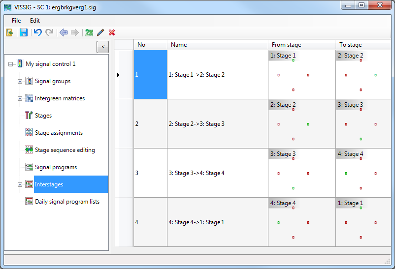
4. Click Interstages in the Navigator.
The interstages are displayed.
5. Right-click the entry of your choice.
6. On the shortcut menu, click the desired entry.
| Element | Description |
|---|---|
| Duplicate | Copy interstage and insert with a new number |
| Edit | Change data of the selected interstage |
| Delete | Delete selected interstage |
| Export | Export graphic of the selected interstage |
7. Edit the interstage:
| Element | Description |
|---|---|
| No. | Number of interstage |
| Name | Name of interstage. The name is taken from the stage sequences in Stage sequence editing in the Navigator (Editing stage sequence). |
| From stage | Source stage of Interstage |
| To stage | Target stage of Interstage |
| Recalculate | After changing a stage, recalculate the stage sequence and update the display. |
8. To edit an interstage, double-click the row with the No. and Name of the interstage.
The editing of switching times is done like the editing of signal group-based signal programs (Editing signal programs).
Functions in the shortcut menu of interstages
1. Right-click in the right panel of the graphic.
The shortcut menu opens.
2. Make the desired changes:
| Element | Description |
|---|---|
| Export | Save interstages as a graphic file (Exporting data from the signal controller editor). |
| Appearance |
Select display:
|
| Resize automatically | The row height is automatically adjusted if you change the window size |
| Show entire signal program | Redraws the signal program and adjusts the row height to the window height. |
|
|
Note: You can export interstages in the menu File > Export > PUA in PUA format. This format is required, for example, for VAP control procedures. |
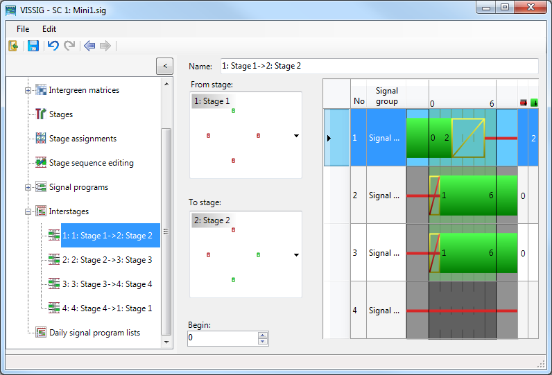
Editing attributes of the selected interstage
1. Select the desired interstage.
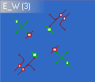
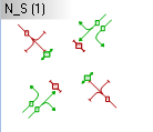
2. Make the desired settings in the two areas From stage and To stage.
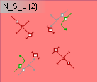
3. If you move the cursor over a stage, the possible source stages and target stages are indicated in color in the list box. The selection of a different source stage or target stage automatically starts a recalculation of the interstage.
|
|
Blue background: Indicates the selected stage. |
|
|
Purple background: Interstage with red background selected. The selection leads to an automatic recalculation of the interstage. |
|
|
White background: This selection does not lead to an automatic recalculation of the interstage. |
|
|
Red background: Indicates a stage which is unsuitable for the interstage. The selection leads to an automatic recalculation of the interstage. An interstage is calculated for an initial state (From stage) and a destination state (To stage). If another initial state or destination state is selected, the interstage must be be redefined. |
|
|
White background: This selection does not lead to an automatic recalculation of the interstage. Black line: The stage is not relevant. |

4. Double-click in the desired stage area of a signal group.
The state of this signal group in the stage is switched. The interstage is automatically recalculated.
With the next steps, you can move the initial state to the left (begin < 0) and the destination state to the right (end > duration of interstage). You can move the initial state to the right until the first state change within the interstage. You can move the destination state to the left until the final state change within the interstage. Switching points are not moved.
5. Select the desired value for the start of the interstage in the Begin field.
6. Select the desired value for the end of the interstage in the End field.
A reduction is possible only to the duration of the longest transition state (Amber/Red-Amber).
|
|
Note: If the state of a signal group in the source stage or target stage is not relevant when calculating an interstage, no signal switch occurs for this signal group. The same signaling state is displayed within the interstage as in the relevant stage. If the state of a signal group is neither relevant in the source stage nor in the target stage, the signaling state is also displayed as not relevant within the interstage. |
