RBC Editor elements
- ► Open the RBC Editor ( >> RBC Editor menuesOpen the RBC Editor1. Make sure that the inpx network file is saved.2. From the menu select Signal Control > Signal Controllers.The Signal Controllers list is opened.3. Double-click the desired RBC signal controller.The Signal Controller dialog is opened.4. Click the Edit signal groups button.The RBC editor is opened. The menues are shown:Menu File (Menu File)Menu Edit (Menu Edit)Menu View (Menu View)Menu Help (Menu Help)Menu FileNew FileOpens a blank PRBC supply file.Warning: If signal groups are assigned to the existing controller in the window when creating a new file, and the signal groups are not recreated within the new controller, signal group information for signal head network objects may be lost.Import FileSupported import file formats:PRBC files (*.prbc): Imports a previously defined PRBC supply file.Backup Files (*.prbc.bak): Imports a previously saved PRBC backup supply file. The backup file is saved automatically when you save your PRBC supply file.Old RBC files (*.rbc): Imports a RBC supply file which was previously defined in a Vissim version before Vissim 2022.Warning: If signal groups are assigned to the existing controller in the window when importing a file, and the signal groups are not contained within the imported controller, signal group information for signal head network objects may be lost.RevertUndo changes and revert to initial version.Save a CopySave your PRBC supply file with the defined name. When creating a new signal controller you must save your RBC supply file before exi ting, if you want to use the signal timings defined in the interface.After the file has been saved with a name, any signal timing changes can be saved by clicking OK in the dialog.When creating a new controller or changing the name of the signal controller PRBC supply file, save your Vissim input file, otherwise the Vissim input file will not use the new PRBC supply file when reopened.PrintPrints your signal timing information to your desired printer.Print PreviewAllows you to view the document that will be printed. There are no options for configuration within this dialog. If Print Selection in the menu is checked, only the items selected in the tree view will be shown.ExitExits the RBC editor without saving the PRBC supply file.Menu EditTip: Undo, Redo: Alternatively, you can use the hotkeys Ctrl+Z, Ctrl+Y.Menu ViewBasic ViewOpens a default basic view settings file, hiding advanced controller features. These hidden features can be shown again by selecting them for display in the tree view.Hide Default and Read-Only rowsSelects exactly those attributes for display which have some non-default value in the current supply.Tree ViewOpens and closes the tree view table selection window.Message PanelOpens and closes the message panel window. When the panel is closed, you can still expand the window, but when it is not expanded you will no longer see the message panel with the tabs with the number of errors, warnings, and messages.Save SettingsSaves the state of your editor to an RBC settings file (*.rbcdialogsettings). These settings can be used by any RBC editor.This changes only the RBC editor display. This does not change nor save any signal timing values.Load Settings Loads the controller display settings file (*.rbcdialogsettings) that was previously saved. This changes only the RBC editor display. This does not change nor save any signal timing values.Menu HelpHelpOpens a browser and displays the Using RBC help topic of the Vissim Help.Tip: In each field of the RBC Editor tables you can press F1 to display the help for the field. © 2025 PTV Planung Transport Verkehr GmbH - Imprint )
The RBC Editor contains the following elements, which are described below:
Notes input field
Enter any information in the Notes input field on the top right-hand corner of the RBC editor. The text is saved within the controller file. This field is not used by the controller or Vissim.
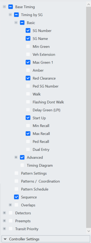
Tree View
The tree view is a layered explorer tree for multi-selection of data groups. The options checked in this view will display the corresponding tables or data in the right hand side of the RBC editor. This is for display purposes only. All data selection layout will be saved in RBC settings file (*.rbcsettings) (Save Settings). The items selected will affect the Print (Print).
- ► Activate the checkboxes of the desired Parameters to edit their values in the tables (Tables).
Controller Settings
You can edit the Frequency and Offset Reference in the Controller Settings area below the tree view.
- ► Click the area Controller Settings.
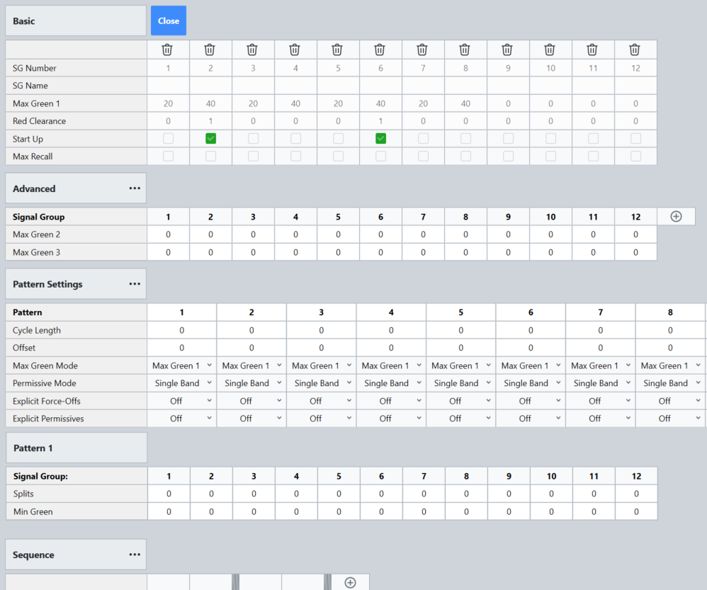
Frequency
|
Determines how many times per second the controller will communicate with Vissim during the simulation. During the communication information about detector calls are passed to the controller and the signal heads indications green, red, amber can be changed.
|
Offset Reference
|
The Offset Reference is defined only once per signal controller and therefore is used for all patterns within the signal controller. The parameter only apply when coordination is used.
This is the point in the cycle where the master cycle timer will be equal to the defined offset time when the controller is coordinated and not in transition (offset seeking). The selections are:
- Lagging Force-Off (LagFO): The reference point will be at the force-off point for the lagging coordinated signal group.
- Leading Start of Green (LeadGreen): The reference point will be at the start of the leading coordinated signal group green (the computed start of green, note that the signal group may actually return to green early if there is lack of demand on opposing movements).
- End of Lagging Red (LagEnd): The reference point will be at the end of Red Clear for the lagging coordinated signal group.
- End of Coordinated Group Red (CoordEnd): The reference point will be at the end of red for the last signal group in the concurrent barrier group with the coordinated signal groups.
|
Tables
- ► Make sure that that the checkboxes for the desired items are selected
in the Tree view.
In the tables, you edit the signal timing data entries (Edit timing data entries).
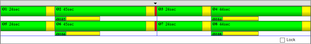
Timing Diagram
- ► Make sure that the Timing Diagramcheckbox within the Tree view ist selected
.
The Timing diagram gives you the ability to view and modify sequence and timing plans through a graphical interface. The timing diagram will display the timing defined within the pattern shown in the Pattern Settings table (RBC Editor elements).
- If a pattern is selected, the split values will be modified.
- If Free-running is selected, the maximum green times will be modified.
Change the Timing
- ► Drag within the Timing Diagram.
Change the size
- ► Select and move the end drag point
.
Reset the size
- ► Right-mouse click within the Timing Diagram and select the desired entry.
Log Panel shows errors, warnings, messages
- ► At the bottom of the editor, click
.
During editing potential risk situations will be checked for and if found they will be logged in the Log panel for review.
The logs for errors and warnings get updated automatically when the problem has been resolved. However, the messages continue to accumulate for the length of the session.
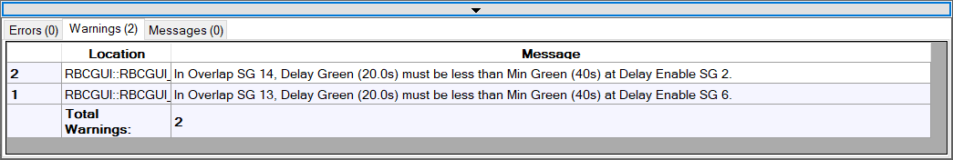
- The Errors table lists errors in the current supply that will prevent the simulation from starting.
- The Warnings table lists warnings about the current supply. Starting a simulation will not fail due to warnings, but the controller behavior may be unexpected.
- The Messages table lists other logged messages regarding the current session.