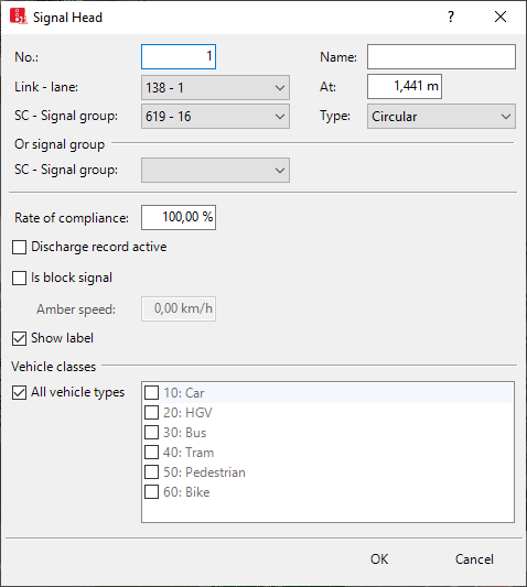
Attributes of signal heads
The Signal Heads window opens when you insert a network object and have selected to have the Edit dialog automatically opened after object creation (Right-click behavior and action after creating an object). By default, only the Signal Heads list is opened.
Into the window, you enter attribute values for the network object. For network objects which have already been defined, you can call the window using the following functions:
- ► In the list of network objects of the network object type, double-click the row with the desired network object.
- ► In the Network editor, select the network object of your choice. Then, on its shortcut menu, click Edit.
The network object may have additional attributes. In the network objects list of the network object type, you can show all attributes and attribute values. You can open the list via the following functions:
- ► On the network object sidebar, right-click the desired network object type. Then on the shortcut menu, click Show List (Shortcut menu in the network object sidebar).
- ► In the Network editor, select the network object of your choice. Then, on its shortcut menu, click Show In List (Selecting network objects in the Network editor and showing them in a list).
- ► On the Lists menu, in the desired category, click the network object type.
In the network objects list of the network object type, you can edit attributes and attribute values of a network object (Selecting cells in lists), (Using lists).
The objects of this object type may have relations to other objects. This is why the attributes list is shown as part of a coupled list (on the left). On the Lists toolbar, in the Relations box, you can show and edit the coupled list with the attributes of the desired relation on the right (see below Showing and editing dependent objects as relation) and (Using coupled lists).

|
Note: In lists, you can use the |

1. Make the desired changes:
| Element | Description |
|---|---|
|
No. |
Unique number |
|
Name |
Designation |
|
Link |
Link for which the signal head has been defined |
|
Lane |
Ln: Number of lane to which you have added the signal head. |
|
At |
Position (Pos): Distance from start of the link or connector |
|
SC - signal group |
Number and name of respective signal controller SC and respective signal group SG |
|
Type |
Display of the signal head in 3D animation during a simulation run or test run:
If the normal signal group of an arrow signal head has the signal state Red or Off and an Or signal group is defined for this signal head, the signal state or the Or signal group is shown as a bar without an arrow. This also applies if the normal signal group is yellow and the Or signal group is red-amber or reversed. |
|
Or signal group |
OrSG:
You can use the Or signal group to model vehicles turning right with green right arrows, which are indicated by their own signal group before and afterwards and by a circular symbol during the actual phase as contractually stipulated. Define two signal heads on different links:
|
|
Compliance rate |
ComplRate: Every vehicle and every pedestrian has an individual random number. This number is between 0.0 (0%) and 1.0 (100%) and is evenly distributed. If this random number is greater than the compliance rate of a signal head, the vehicle or the pedestrian will ignore the respective signal head. Minimum value: 0.0 = 0% Maximum value: 1.0 (default value) = 100% If the compliance rate is below 100%, use conflict areas to model intersection control (Using conflict areas). |
|
Discharge record active |
DischRecAct: |
|
Is block signal |
Is block signal (IsBlocksig): |
|
Amber speed |
Block signal amber speed (vAmberBlock): Speed assigned to a train when it travels past the block signal and the state of the block signal is Amber (Modeling railroad block signals). The Is block signal option must be selected. Default value 0 km/h. |
|
Label |
|
|
Vehicle classes |
VehClasses: Vehicle classes for which the signal head is valid. For example, you can define a separate signal for buses on a link, which should be ignored by private transportation. The option All Vehicle Types is a virtual vehicle class that automatically includes all new vehicle types and vehicle types that have not been assigned a vehicle class yet. |
|
Pedestrian classes |
PedClasses: If the signal head is defined on a link for which the attribute Is pedestrian area is selected: For the simulation of pedestrians, the pedestrian classes that are valid for the signal head. |
|
Slow down distance |
SlowDownDist: In list only: Distance from stop line at which pedestrians start to reduce their speed in order to stop at the stop line. Default 3 m. |
|
Lane width |
LnWid: only in the list: Width of the lane at the position of the marker of the signal head |
|
Rotation angle |
RotAngle: only in the list: Horizontal rotation angle of the link segment for which the signal head is defined |
 Is the
  If this option is not selected, the label for the signal head is hidden if the label for all signal heads is selected.
2. Confirm with OK.
Showing and editing dependent objects as relation
The attribute and attribute values of this network object type are shown in the list on the left, which consists of two coupled lists.
1. In the list on the left, click the desired entry.
The list on the right contains attributes and attribute values of network objects, and/or base data allocated to the network object selected in the list on the left (Using coupled lists):
- Vehicle classes (Defining the vehicle class)
- Pedestrian Classes (Attributes of pedestrian classes)
The attributes are described further above.
2. On the list toolbar, in the Relations list, click the desired entry.
3. Enter the desired data.
The data is allocated.
Superordinate topic:
Modeling signal groups and signal heads
Information on editing:
Zooming into signal heads and detectors of a signal controller
