Defining right of way for conflict areas using major flow
Vissim automatically allocates the status Passive to conflict areas (Using conflict areas). When you switch to the Insert mode of conflict areas, in the network editor, Vissim displays passive conflict areas in yellow. You can change this status for any conflict area and thus control the right of way. To make sure that you do not have to do this for each conflict area at each intersection and/or node separately, you can define the direction of the major flow and thus change the right of way of conflicting flows in the conflict areas. This sets the status of the conflict areas along the major flow to green and the conflict areas of the minor flow to red, giving priority to the link along the major flow, while the minor flow is required to yield. This is also possible for several consecutive nodes.
Defining conflict areas and/or two stage control
When you define the major flow in the network editor using the following steps, you can specify whether Vissim should define only the necessary conflict areas, only the two stage control, or the necessary conflict areas and the two stage control at the node.
Prerequisites for two stage control
To define a two stage control, nodes must be defined at the desired intersections (Defining nodes).
Properties of the two stage control
- Vissim inserts a signal head in the node for turns 1 m before the first conflict area.
- If the node is a branching, Vissim inserts the signal head upstream of the conflict area of the junction on the link, but not on specific lanes.
- If the area between conflict areas or between conflict areas and incoming or outgoing connectors is shorter than 1 m, Vissim inserts the signal head further upstream.
- If Vissim inserts the signal head further upstream so that it is not located within conflict areas, the signal head can be located directly at the beginning of the conflict area upstream, the distance of 1 m is not possible.
- Vissim inserts signal heads regardless of the status of the conflict areas
Vissim inserts a detector if the turn is not a major flow turn but has a conflict with the major flow. This also applies at a pedestrian crossing that has a conflict with the major flow. Thus all turns, which run parallel to the major flow and have no conflict with it, get green at the same time as the major flow. The detector is 2 m long on a link for vehicles. The detector is 1 m long on a link for which the as pedestrian area attribute is selected. Vissim inserts the detector on the same link as the corresponding signal head.
- ► For a branching, if the To-link and the From-link of the connector overlap, set the Conflict type (manual) attribute to Branching for these conflict areas and deactivate the Conflict type determined automatically attribute.
If a signal head is moved upstream because it would be located within one or more conflict areas, e.g. branchings, no minimum distance of 1 m between signal head and conflict area applies in this case. The signal head can then be located directly at the beginning of the conflict area starting further upstream.
During the definition of the objects in the network editor, the Short help is displayed, in which the necessary steps are described. You can show and hide the short help (Short help button in the Network editor toolbar).
1. On the Network editor toolbar, click the Conflict areas button.
The conflict areas are displayed in color in the Network Editor. Per default, conflict areas that have not yet been allocated a right of way are highlighted in yellow.
2. On the network editor toolbar, on the very left, click the Define major flow button  .
.
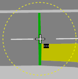
If you move the mouse pointer to a link or connector, a circular selection area is displayed around the mouse pointer.
- You can hold down the Shift key, rotate the mouse wheel, and change the size of the circular selection area.
- You can rotate the mouse wheel to zoom in and out.
- The
 symbol to the right, below the mouse pointer, indicates that you can select the starting point of the major flow on a link or connector.
 - The Define major flow section is displayed in the upper left corner of the Network Editor.
- Instead of setting conflict areas and 2-stage control of the nodes of the major flow in the Define major flow section (as described in the following), you can click the
 symbol at each node in the major flow until the desired option is shown.
 - If you do not wish to set conflict areas and/or 2-stage control for all nodes and want to remove a node from the selection of nodes in the major flow, next to the node, click the
 symbol. The symbol changes to
  . To add the node to the selection again, click .
3. Move the mouse pointer to the position upstream of the conflict areas of the link or connector in order to define the starting point of the major flow.
Green start sections are displayed on the links and connectors that lie within the circular selection range. Here you can start to define the major flow.
4. Click the position where you want the major flow to start.
5. Point to the position on the link or connector where you want to end the definition of the major flow.
There can be several successive links and connectors and several nodes between the start and destination section of the major flow. A green ribbon indicates the major flow.
6. Click the position on the link or connector where you want to end the definition of the major flow.
The conflict areas in the area of the major flow are hatched in color:
- Green: major flow (right of way)
- Red: minor flow (yield)
If connectors for left-turners end downstream of connectors for right-turners, individual conflict areas may still have the status Passive.
The  symbol to the right below the mouse pointer indicates that you can end the definition of the major flow.
If the green ribbon of the major flow passes through a Nodes network object, all conflict areas, that lie within this node or start or end here, will be taken into consideration.
7. If you do not want to change the status for all conflict areas of such a node, but only for the conflict areas that are within the green ribbon, hold down the Ctrl key and click theNode network object.
The conflict areas outside the green ribbon are displayed in yellow showing their Passive status.
You can perform the following step more than once.
8. If you want to include conflict areas that are not located in a Node network object, move the mouse pointer so that the conflict areas are located in the circular selection area and click.
9. In the section Define major flow, enter the desired values:
| Element | Description |
|---|---|
|
MinGreenMajor |
Minimum green time major flow: Minimum green time for the major flow. Only valid for certain signal controller types. Default: 5.0 |
|
MinGreenMinor |
Minimum green time minor flow: Minimum green time for the minor flow. Only valid for certain signal controller types. Default: 5.0 |
|
ClearTmMajor |
Clearance time major flow: Waiting time after green of the signal group for the major flow before a conflicting signal group gets green. Default: 10.0 |
|
ClearTmMinor |
Clearance time minor flow: Waiting time after green of the signal group for the minor flow before a conflicting signal group gets green. Default: 5.0 |
10. In the Define major flow section, click  .
.
The hatching is removed. In the Conflict areas list, the status of the conflict areas and the colors in the columns Link A and Link B are displayed according to the Status attribute.
If the major flow uses turning links and connectors, the following applies:
- If the conflict area includes more than two turns and Vissim calculates a different status for them, Vissim the status is set to Passive. The following applies for a junction’s conflict area: If one of the two link segments of the conflict area are part of the major flow, the link of this link segment has priority (green).
- If a conflict area applies to several turns that allow different right-of-way rules and/or the right of way cannot be clearly allocated, Vissim gives advanced warning. In the Messages window, you can view the warnings for the conflict areas affected.
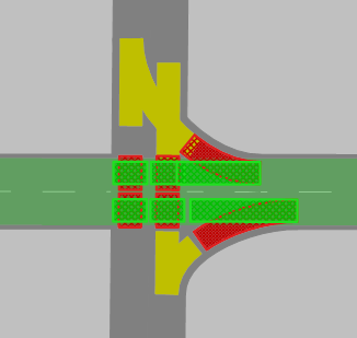
11. Check the status of the conflict areas and select the desired status. Check the following conflicts:
|
Left-turns change from a minor flow onto the left lane of a major flow link, right turns coming from the opposite direction of the minor flow change onto the right lane of the multi-lane link. The major flow running straight from left to right has priority. Example:
|
||
|
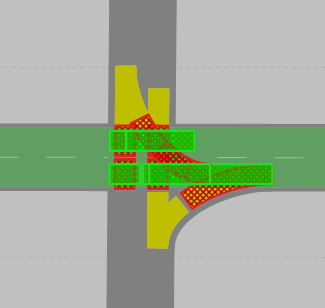
Left turns drive from a minor flow onto a lane of a major flow, right turns coming from the opposite direction of the minor flow drive onto the same lane. The major flow running straight from left to right has priority. Example:
|
||
|
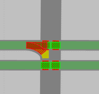
Right turns coming from a major flow cross a parallel running major flow (e.g. vehicle crosses a cycle path). The major flow running parallel and straight from left to right also has priority. Example:
|