Attributes of pavement markings
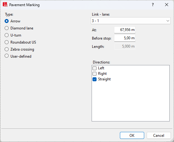
The Pavement Marking window opens automatically when you insert a network object and have selected to automatically open the Edit dialog after object creation (Right-click behavior and action after creating an object). By default, only the Pavement Markings list is opened.
Into the window, you enter attribute values for the network object. For network objects which have already been defined, you can call the window using the following functions:
- ► In the list of network objects of the network object type, double-click the row with the desired network object.
- ► In the Network editor, select the network object of your choice. Then, on its shortcut menu, click Edit.
The network object may have additional attributes. In the network objects list of the network object type, you can show all attributes and attribute values. You can open the list via the following functions:
- ► On the network object sidebar, right-click the desired network object type. Then on the shortcut menu, click Show List (Shortcut menu in the network object sidebar).
- ► In the Network editor, select the network object of your choice. Then, on its shortcut menu, click Show In List (Selecting network objects in the Network editor and showing them in a list).
- ► On the Lists menu, in the desired category, click the network object type.
In the network objects list of the network object type, you can edit attributes and attribute values of a network object (Selecting cells in lists), (Using lists).
The objects of this object type may have relations to other objects. This is why the attributes list is shown as part of a coupled list (on the left). On the Lists toolbar, in the Relations box, you can show and edit the coupled list with the attributes of the desired relation on the right (see below Showing and editing dependent objects as relation) and (Using coupled lists).

|
Note: In lists, you can use the |

| Element | Description |
|---|---|
|
Type |
Defines the geometric symbol shown in the Vissim network
|
|
Directions |
Arrow directions (ArrowDir): This is only relevant for the Arrow type: This defines the geometric symbol shown in the Vissim network. If you select several directions, these are combined in the arrow.
|
|
At |
Position (Pos): Position distance from the beginning of the link [m] |
