Rules and examples for defining meso network nodes
Meso network nodes must be modeled correctly for Vissim to be able to model conflicts realistically in mesoscopic simulation. The level of correctness has a decisive impact on the result of dynamic assignment in mesoscopic simulation. Follow the rules for defining meso network nodes when you manually define individual meso network nodes in the Network editor. Before starting to model meso network nodes it is necessary to look at the examples and read the descriptions of correct and incorrect definitions for meso network nodes. Follow the instructions for modeling meso network nodes (Modeling meso network nodes).
Rules for defining meso network nodes
- Rule 1: Meso network nodes must be defined everywhere on a link where more than one connector begins or ends.
Exception - PT lay-by-stops: It is not necessary to define meso network nodes at the starting point and the end of a connector, which runs towards a link of a lay-by-stop, as well as at the starting point and the end of a connector, which runs from the lay-by-stop to the original link.
- Rule 2: For each intersection, at least one meso network node must be defined. Depending on the node geometry, several meso network nodes may be defined.
For non-signalized intersections the following applies: All conflict areas must be defined. In order to decide which conflict areas shall lie within a separate meso network node, check the following:
- Where is the vehicle supposed to stop? For all turn conflicts, the vehicle stops at the meso network node. Model the meso network node so that its edge roughly corresponds to a stopping position of the vehicle in reality, e.g. a stop line.
- Are the incoming meso edges used by vehicles with the right of way to reach the meso network node relevant for all turn conflicts in the meso network node? The size and positioning of the node determine which meso edges are perceived as edges with vehicles that have the right of way (Meso conflict relevant and non-relevant edges).
- How long is the travel time on the incoming meso edge used by vehicles with the right of way to reach to meso network node? This travel time should be longer then the meso critical gap of the subordinate flow.
For signalized intersections note that the decisive factors are the stop position and storage capacity. The vehicle always stops at the meso network node. If the real situation cannot be modeled with one meso network node only, model several nodes, e.g. for a channelized right turn.
- Rule 3: On turn meso edges, the following properties must not change:
- the number of lanes
- the link behavior type
- the meso speed, if the meso speed model Link-related is selected (Car following model for mesoscopic simulation)
This means the Defining links of the meso turn must each have the same value (Attributes of meso turns).
|
|
Note: Please note the limitations and information that apply for defining meso network nodes (Defining meso network nodes). |

Examples of applying the rules for defining meso network nodes
The following examples show how the rules are applied when you model intersections. First, you are shown how the position of a meso network node impacts where at the conflict area a vehicle stops and which edges it perceives as relevant:
- Consequences of correct and incorrect positioning of meso network nodes
- Meso conflict relevant and non-relevant edges
Then, you are given an explanation of how the rules impact the modeling of different types of intersections. For different network objects, the impact of rules on the meso graph structure and on simulation is demonstrated:
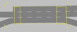
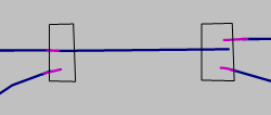
- Nodes in areas where the number of lanes changes
- Modeling connectors in meso network nodes
- Modeling a signalized intersection
- Modeling intersections with lane widening
- Modeling intersections with bypass and channelized turn
- Modeling roundabouts
- Modeling reduced speed areas on links
- Modeling signal controllers on links
Consequences of correct and incorrect positioning of meso network nodes
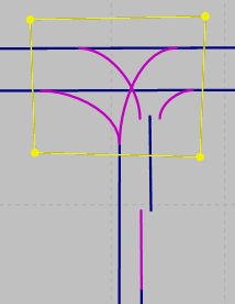
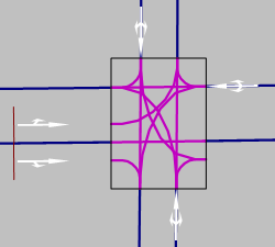
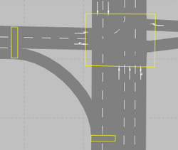
The following example describes the meaning of travel time as a meso critical gap on an edge for a 3-leg intersection with nine turn conflicts. Nine meso network nodes have been manually defined at the nine turn conflicts (1 to 9):
![]()
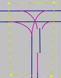
This type of modeling is not recommended if the travel time on the edge leading into the meso network node is shorter than the meso critical gap of the conflict in the meso network node. This leads to incorrect modeling of the conflicts in mesoscopic simulation. It is illustrated in the following figure and explained in the description given below it.
|
Situation:
|
|---|
|
The conflicts are not modeled correctly in mesoscopic simulation:
|
 The vehicle is coming from below and turns upward left:
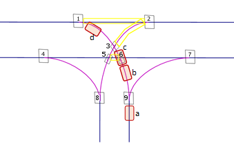
If the vehicle stops at a wrong position and the travel time at the edge leading into the meso network node is very short, the travel time acts as a critical gap. Vissim is then unable to model the conflicts in mesoscopic simulation realistically (as illustrated in the figure above).
If, for instance, no meso network node is defined for node 3 (at top of figure), Vissim does not recognize the conflict there and the conflict is ignored in mesoscopic simulation.
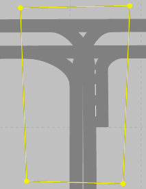
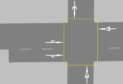
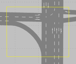
Solution: If for these types of intersections, with short edges between conflicts, only one meso network node is defined, Vissim is able to model conflicts realistically in mesoscopic simulation. With one meso network node only, the left-turning vehicle has only one stop position in all subsequent conflicts. The travel times at the incoming edges are long enough and the vehicle stops at the correct position. This is illustrated in the following figure and explained in the description given below it.
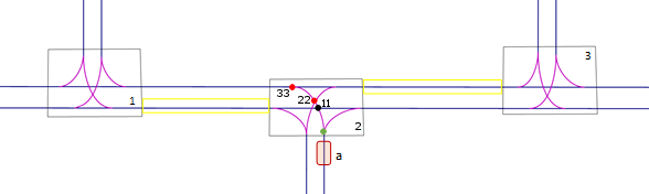
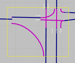
Correct modeling: The travel times at all edges leading into the node at conflict points are long enough. This ensures that the vehicle stops at the correct positions:
- With conflict 11 in the black dot, the vehicle is aware of the edge leading from node 1 into node 2. If the travel time on this edge is longer than the meso critical gap for the conflict, the specified value is used as critical gap, e.g. 3.5 s.
- With conflicts 22 and 33 in the red dots, the vehicle is aware of the incoming edge between nodes 3 and 2. If the travel time on this edge is longer than the meso critical gap for the conflict, the specified value is used as critical gap, e.g. 3.5 s.
Meso conflict relevant and non-relevant edges
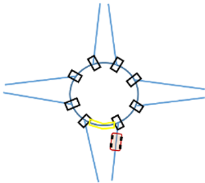
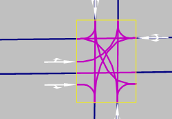
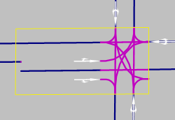
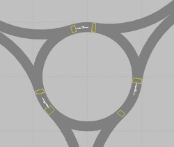
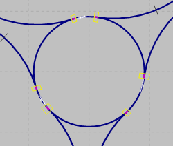
This example shows a roundabout (right-hand traffic) for which multiple meso network nodes have been correctly positioned, in the figure on the left. In the figure on the right, only one meso network node has been positioned across the roundabout. The following two figures show the meso edges the vehicle is aware of when it stops at the meso network node:
- Correctly modeled: The modeling in the figure on the left ensures that the vehicle is aware of the relevant meso edge (yellow between the two meso network nodes), leading directly into the correctly positioned meso network node at which the vehicle stops. The correct meso critical gap is used.
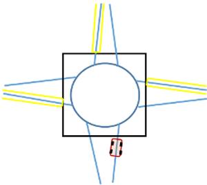
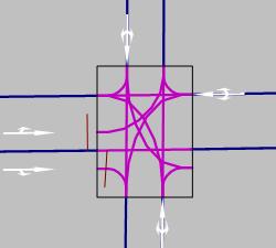
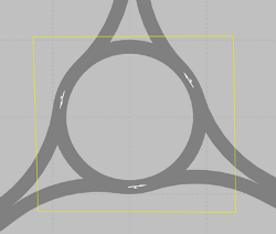
- Incorrectly modeled: The modeling in the figure on the right does not allow the vehicle to become aware of the relevant meso node. For conflicts in the meso network node, e.g. the entry of the vehicle into the roundabout, the vehicle is only aware of non-relevant meso edges (the three meso edges highlighted in yellow that lead into the meso network node from the left, top and right). The vehicle cannot become aware of the relevant node as shown in the figure on the left. Thus, it cannot take a correct meso critical gap into account. The vehicle stops at the meso network mode and gives priority to the vehicles coming from the right, top and left, as it is only aware of their meso nodes.
|
Correct: Vehicle is aware of relevant meso edge (yellow between the two bottom meso network nodes)
|
Incorrect: Vehicle is only aware of non-relevant meso nodes (yellow)
|
|---|---|
|
|
|
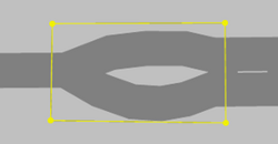
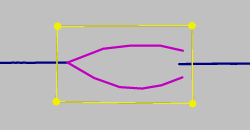
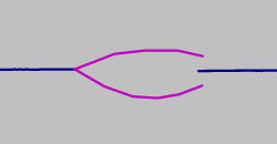
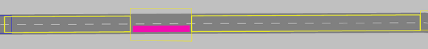
Nodes in areas where the number of lanes changes
There are different ways to model areas in which the number of lanes changes. These impact dynamic assignment in mesoscopic simulation in different ways. This is illustrated in the following figure and explained in the table listed below it.
Connector connects a double-lane link with a single-lane link:
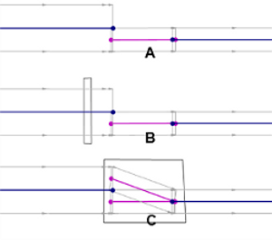
The vehicle may only change lane at the end of a meso node. This applies for meso nodes generated automatically by Vissim and for modeled meso network nodes (Mesoscopic node-edge model).
| Modeling | Situation | Mesoscopic simulation |
|---|---|---|
| A |
|
|
| B |
|
|
| C |
|
|
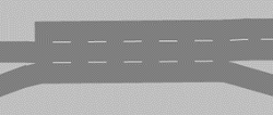
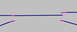
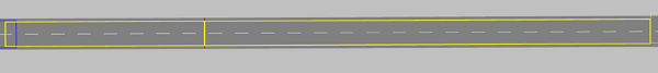
Connector connects a single-lane link with a double-lane link:
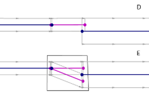
| Modeling | Situation | Mesoscopic simulation |
|---|---|---|
| D |
|
|
| E |
|
|
Modeling connectors in meso network nodes
| Rule | Description | |
|---|---|---|
| 1 |
Meso network nodes must be defined everywhere on a link where more than one connector begins or ends. |
|
|
|
|
|
|
Correct:
|
False:
|
|


| Rule | Description | |
|---|---|---|
| 1 |
Meso network nodes must be defined everywhere on a link where more than one connector begins or ends. |
|
|
|
|
|
|
Correct:
|
False:
|
|
| Rule | Description | |
|---|---|---|
| 1 |
Meso network nodes must be defined everywhere on a link where more than one connector begins or ends. |
|
|
|
If the transition from a one-lane link to a two-lane link is modeled across two connectors, these must lie entirely within the node. |
|
|
Correct:
|
False:
|
|

| Rule | Description | |
|---|---|---|
| 3 |
On turn meso edges, the following properties must not change:
|
|
|
|
|
|
|
Correct:
|
False:
|
|
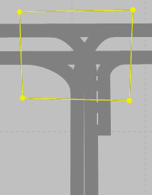
Modeling a signalized intersection
| Rule | Description | |
|---|---|---|
| 2 |
For each intersection, at least one meso network node must be defined. Depending on the node geometry, several meso network nodes may be defined. |
|
In the figure at the bottom right this means: If the signal heads are 10 m from the meso network node of the intersection, Vissim automatically generates a meso node at the signal heads. The edge between the two nodes is then 10 m long. The travel time of a vehicle driving at 10 m/s on this edge is 1 s. This second acts as a critical gap for the vehicle approaching from the right and turning left, regardless of the actual meso critical gap defined, as the vehicle cannot tell whether, beyond the meso node, there is a vehicle approaching from the left that it must yield to. A critical gap of 1 s does not give the vehicle enough time to yield. Solutions: a) Position the signal heads within the meso network node or b) reduce the distance between signal heads and meso network nodes to below 5 m or c) ensure that the length of the edge leading into the node is long enough to create a travel time on the edge that is longer than the meso critical gap of the turn conflict in the node. |
||
|
Correct: The signal heads are positioned within the meso network node or at a maximum of 5 m from it
|
Not recommended: The signal heads are positioned at a distance of more than 5 m from the meso network node
|
|


Modeling intersections with lane widening
| Rule | Description | |
|---|---|---|
| 2 |
For each intersection, at least one meso network node must be defined. Depending on the node geometry, several meso network nodes may be defined. |
|
|
||
|
Correct:
|
False:
|
|

Modeling intersections with bypass and channelized turn
| Rule | Description | |
|---|---|---|
| 2 |
For each intersection, at least one meso network node must be defined. Depending on the node geometry, several meso network nodes may be defined. |
|
|
||
|
Correct:
|
Not recommended:
|
|

Modeling roundabouts
|
|
Note: The following tips refer to the modeling of simple roundabouts, e.g. those with a single lane, with no or only one bypass and few entries and exits. To model more complex roundabouts or roundabouts whose conflicts cannot be modeled correctly in mesoscopic simulation, define sections and perform a hybrid simulation (Using hybrid simulation). |
| Rule | Description | |
|---|---|---|
| 2 |
For each intersection, at least one meso network node must be defined. Depending on the node geometry, several meso network nodes may be defined. |
|
|
||
|
Correct:
|
False:
|
|
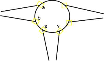
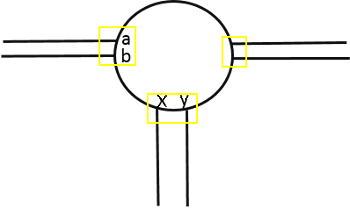
Model meso network nodes for a roundabout depending on the distance between the exit and the next entry and according to approach A or approach B. The is illustrated in the figures and their descriptions below:
| Description of approach A | |
|---|---|
|
If the distance between the exit and next entry downstream is large enough, define a meso network node for the exit and another one for the entry. This is the case in the following situations:
|
|
|
Correct:
txy > tCG(y) or tbx < txy
|
When you export a network from Visum and import it into Vissim via ANM import, Vissim automatically generates meso network nodes based on approach A. These nodes do not require any subsequent editing (Generated network objects from the ANM import). The table lists different speeds to illustrate the minimum distance between exit x and the next downstream entry y with a critical cap of 3.5 s, in order for approach A to meet condition 1:
| Veh speed on roundabout lane | min. distance [m] x-y to meet condition 1 | |
|---|---|---|
| m/s | km/h | |
| 1 | 3.6 | 3.5 |
| 2 | 7.2 | 7.0 |
| 3 | 10.8 | 10.5 |
| 5 | 18 | 17.5 |
| 7 | 25.2 | 24.5 |
| 10 | 36 | 35.0 |
| 14 | 50.4 | 49 |
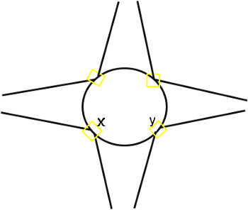
| Description of approach B | |
|---|---|
|
If the distance between the exit and next entry downstream is not large enough, define a common meso network node for both the exit and entry. This is the case, when the two following situations happen at the same time:
|
|
|
Correct:
tbx > txy and txy < tCG(y)
|
The two following figures show wrong approaches to define meso network nodes: These approaches produce incorrect results when used to model conflicts in mesoscopic simulation:
|
Incorrect approach 1: The distance between the entry and the next exit downstream is not large enough. As a result, too many conflicts arise at each of the nodes:
Solution: If the entry and the next exit downstream are very close to each other, use approach A, even if this results in short edges between the meso network nodes. In that case, at each of the two meso network nodes, there will be only one merging or branching conflict. At the branching conflict, the short edge leading out of the meso network node does not pose a problem. |
|
|
|
|
|
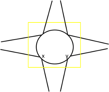
Figure below Incorrect approach 2: Only a single meso network node has been defined for all conflicts in the roundabout. Effect: Conflicts are not modeled realistically, vehicles stop at wrong positions and for conflicts, the time gap is based on non-relevant edges. |
|
|
|
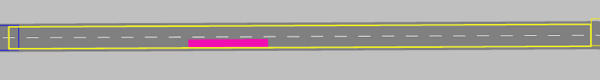
Modeling reduced speed areas on links
| Description | |
|---|---|
|
|
|
|
|
Modeling signal controllers on links
| Description | |
|---|---|
|
|
|
