Attributes of detectors
The Detectors window opens automatically when you insert a network object and have selected to automatically open the Edit dialog after object creation (Right-click behavior and action after creating an object). By default, only the Detectors list is opened.
Into the window, you enter attribute values for the network object. For network objects which have already been defined, you can call the window using the following functions:
- ► In the list of network objects of the network object type, double-click the row with the desired network object.
- ► In the Network editor, select the network object of your choice. Then, on its shortcut menu, click Edit.
The network object may have additional attributes. In the network objects list of the network object type, you can show all attributes and attribute values. You can open the list via the following functions:
- ► On the network object sidebar, right-click the desired network object type. Then on the shortcut menu, click Show List (Shortcut menu in the network object sidebar).
- ► In the Network editor, select the network object of your choice. Then, on its shortcut menu, click Show In List (Selecting network objects in the Network editor and showing them in a list).
- ► On the Lists menu, in the desired category, click the network object type.
In the network objects list of the network object type, you can edit attributes and attribute values of a network object (Selecting cells in lists), (Using lists).
The objects of this object type may have relations to other objects. This is why the attributes list is shown as part of a coupled list (on the left). On the Lists toolbar, in the Relations box, you can show and edit the coupled list with the attributes of the desired relation on the right (see below Showing and editing dependent objects as relation) and (Using coupled lists).

|
Note: In lists, you can use the |

The basic attributes of the network element are shown in the upper area of the window and in the list of network objects for the particular network object type.
| Element | Description |
|---|---|
|
Port no. |
Physical Port number (PortNo) of the detector, which identifies the detector in the control procedures. If multiple detectors of a signal controller are available via the same number, they behave as if they are connected in parallel to one entry port of the control device (logical OR-operation). |
|
Name |
Designation |
|
Length |
Length of the detection range of a detector. The value 0.000 is e.g. permissible and useful for modeling trolley wire contacts and pedestrian sensors. These are represented in the network as thin horizontal lines. |
|
SC |
Signal controller to which detector is assigned. If in the Type box, > PT Calling Pt. is selected, the SC box is deactivated. PT calling points do not belong to a specific signal controller. |
|
Type |
Type: Select detector type (Modeling PT lines):
|
Location tab
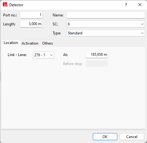
The list in the tab contains, amongst others, the following attributes:
| Element | Description |
|---|---|
| Link | Link, in which the detector is located |
| Lane | Ln: Number of lane on which the detector is installed. |
| At | Position (Pos) Distance from start of the link or connector |
| Before stop | Distance in front of stop line (DistStopLine): Distance of the front edge of the detector to the next signal head of its signal controller on its lane, if a signal head exists |
Activation tab for vehicles
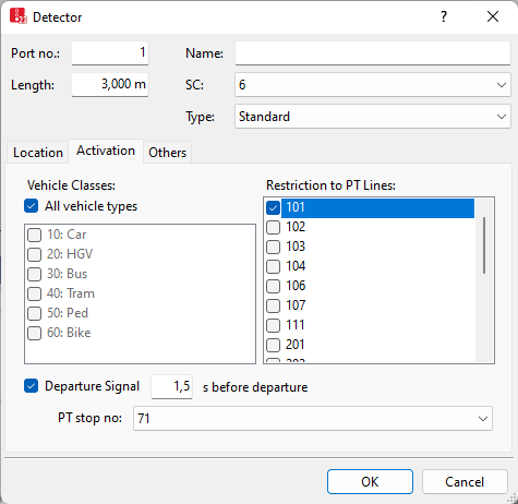
The list in the tab contains, amongst others, the following attributes:
| Element | Description |
|---|---|
| Vehicle Classes | VehClasses: Vehicle classes detected by detector |
| Restriction to PT Lines: |
PTLines: One or multiple PT lines, for which the detector shall be relevant. Thus vehicles of these PT lines are only detected if their vehicle class is selected. |
|
Departure Signal |
The time the door is closed can thus be determined via the detector. |
 If this option is selected, the detector triggers an impulse for closing the doors of the PT vehicle under the following conditions:
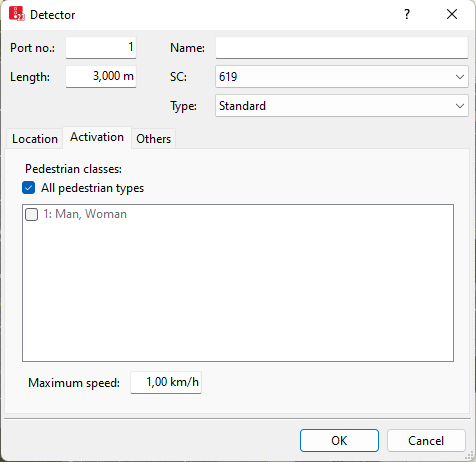
Activation tab for pedestrians
A detector defined for a link with the attribute Is pedestrian area is used to model pedestrians pressing a crosswalk button. Here pedestrian classes are displayed.
1. Make the desired changes:
| Element | Description |
|---|---|
| Pedestrian Classes | Pedestrian classes detected by detector. A pedestrian is recognized by the detector only if the pedestrian type belongs to a selected pedestrian class. |
| Maximum speed |
If the pedestrian falls below this speed, a registration is transferred. The pedestrian requests a green light. If the pedestrian then exceeds this speed before the signal controller switches to green, a deregistration is transferred. The maximum speed applies only to links used as pedestrian areas. The default value of 1.0 km/h prevents slow-moving pedestrians coming from the other side of the pedestrian crossing, for example, from triggering a call again. |
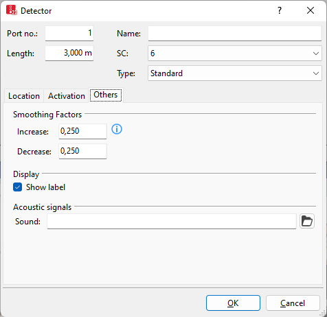
Others tab
2. Make the desired changes:
| Element | Description |
|---|---|
|
Smoothing Factors |
SmthFactDecr, SmthFactIncr: Factors for the exponential smoothing of occupancy values, which is conducted for individual control procedures (Exponential smoothing of detector occupancy rates).
|
| Label |
|
| Sound file (Sound) |
SoundFile: Wavetable sound file *.wav, which is played each time a vehicle is detected by the detector. This file is saved in the same directory as the network file *.inpx. A sound card or suitable Microsoft Windows driver must be installed. |
 If the option is not selected, the label for the detector is not displayed, even if the label for all detectors is selected.
3. Confirm with OK.
The network object has additional attributes that you can show in the Attributes list. Among them are the following for example:
| Element | Description |
|---|---|
|
Presence |
Presence state:
A vehicle is located on a detector, if the following conditions apply:
A pedestrian is considered on a detector, if the center of the pedestrian is located within the rectangle that defines the length of the detector and the width of the lane on which the detector is located. Ensure that the detector is at least as long as the distance a pedestrian can walk within a simulation time step back. In addition, account for the maximum possible speed of the pedestrian at this position. If the detector dimensions are too short, meaning that in one time step, the center of the pedestrian will be in front of the detector and in the the next time step, the pedestrian will be behind it (having already passed it), the detector will not be able to detect the pedestrian. In front of and behind refer to the visually assessed walking direction on the pedestrian link. As pedestrians have no link coordinate, Vissim cannot determine whether the walking direction is towards or away from the detector. |
| Detection |
Detection state:
|
|
Impulse |
Impulse state:
|
| Gap time |
Time: Period [s] after the attribute Presence (Presence state) had the value Active. 0 = Presence attribute is Active. |
| Occupancy |
Occ: Period [s] that has passed since occupancy of the detector. 0 = The detector is not occupied (Presence attribute = Passive). Always 0 for detectors of the type PT Calling Pt. |
| Occupancy rate |
OccupRate: Proportion of time the detector was occupied during the last simulation second. The occupancy rate is exponentially smoothed based on each simulation second. Value range 0 to 100 % |
Showing and editing dependent objects as relation
The attribute and attribute values of this network object type are shown in the list on the left, which consists of two coupled lists.
1. In the list on the left, click the desired entry.
The list on the right contains attributes and attribute values of network objects, and/or base data allocated to the network object selected in the list on the left (Using coupled lists):
- Vehicle classes (Using vehicle classes)
- Pedestrian classes (Using pedestrian classes)
- Public transport lines (Modeling PT lines)
The attributes are described further above.
2. On the list toolbar, in the Relations list, click the desired entry.
3. Enter the desired data.
The data is allocated.
