To manage scenarios, you can use the Scenario GUI.
You can access the GUI by:
- Left clicking a Scenario icon on the map.
- Clicking ADD in the LAYER OPTIONS area of the Scenarios layer.
- Run the operation → Showing a selected item
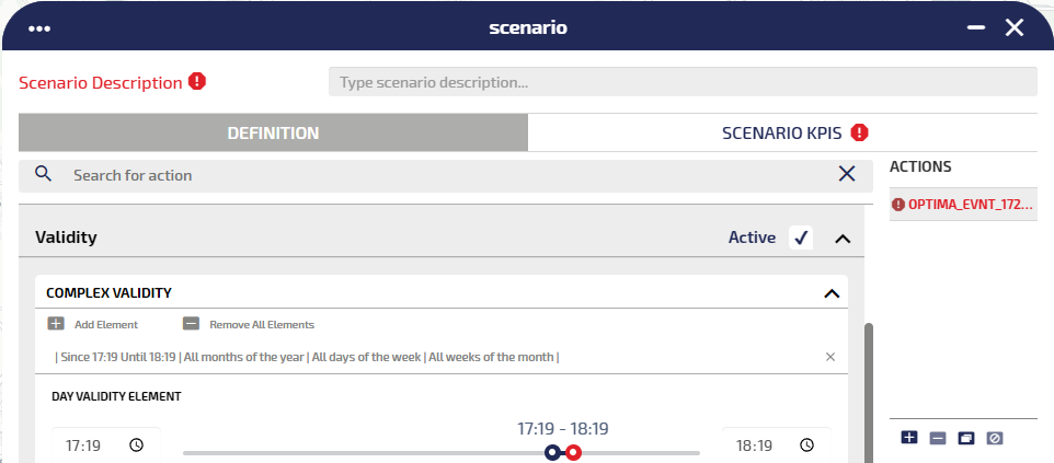
Defining a scenario means creating one or more Actions. Each action is very similar to a real time event.
The main difference is that the validity of a scenario can be specified only as a small subset of the complex validity available in real time events, as shown in the image:
Tip: For all types of scenarios, with the exclusion of the DEMAND type, multiple time segments can be added to the validity definition, and associated through the logical AND.
On the GUI you can define:
- A set of actions associated to the scenario, through the DEFINITION tab.
- A set of KPIs associated to every action, through the SCENARIO KPIS tab (see → Adding a KPI).
Important: You can save a scenario ONLY if at least one KPI is associated to at least one action.
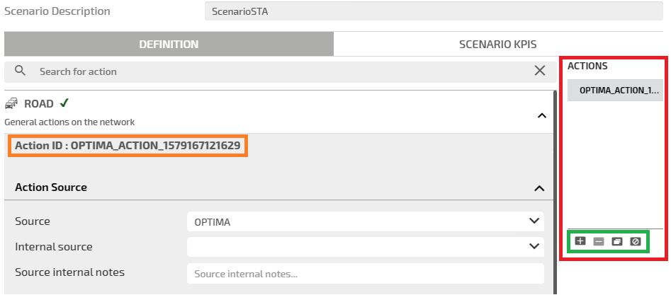
In the GUI you can recognize some main elements, such as:
-
The type of action:
- The ROAD accordion pane.
- The REROUTING accordion pane.
- The SIGNAL accordion pane.
- The DEMAND accordion pane.
- Action ID (orange box).
- Actions involved (red box).
- Basic operations on the list of actions involved (green box).
|
Icon |
Description |
|---|---|
|
|
Add a new action to the list. |
|
|
Remove the selected action from the list. Caution: The list cannot be empty, at least one action must be present for each scenario. |
|
|
The action selected from the list has terminated. |
|
|
Add a new action by cloning the one selected from the list. |
You can set several attributes to configure an action. These attributes are grouped under five sections (accordion panes):
- Action Source
- Validity
- Publication Validity
- Location
- Description
You can open any section and set the related attributes in any sequence.
When you have set the necessary attributes, click SAVE to confirm.
Important: It is mandatory to set some attributes. If the mandatory attributes are not set, they are indicated in RED and marked with a warning sign. In this condition, the configuration of the event cannot be saved.
Set the action source.
|
Option |
Description |
|---|---|
|
Source |
Select the desired action source from the set of values listed in the combo-box. By default, Optima is selected. |
|
Internal source |
Select an internal source from the list for internal use only. You can also add a new source by typing a name; click Enter and OK to confirm the new internal source. Important: You cannot remove an internal source you have just added. |
|
Source internal notes |
Add notes to the internal source, if necessary. Tip: These notes are related to the edited event only, not to the source itself. |
Enter the validity time period of an action.
|
Option |
Description |
|---|---|
|
Active |
By default, the action is set to active. An inactive action has no effect on the forecast engine, the shortest path search, etc. |
|
Complex validity |
Expand this section to provide more detailed validity information. You can set different partitions in the validity time period (see Setting_partition_validity_time_period). Important: Complex validity is not enabled for DEMAND events. |
|
Copy to Public Validity |
Click COPY TO PUBLIC VALIDITY to export the complex validity partitions settings to the Publication Validity section. Caution: Existing data might be overwritten. |
In case of DEMAND events, the validity is pre-set with a "one hour interval" starting from the current creation time.
If the user forces the time interval to be exactly 24 hours, the system provides a diagnostic tool-tip (associated to the Validity label) showing that validity must last strictly less than 24 hours.
According to the action type chosen, you can manage different sets of information:
- ROAD or REROUTING
- SIGNAL
- DEMAND
Important: If you are defining a scenario based on SIGNAL, the associated Description section is depends upon the choice made in the Location section (→ Location section: SIGNAL actions).
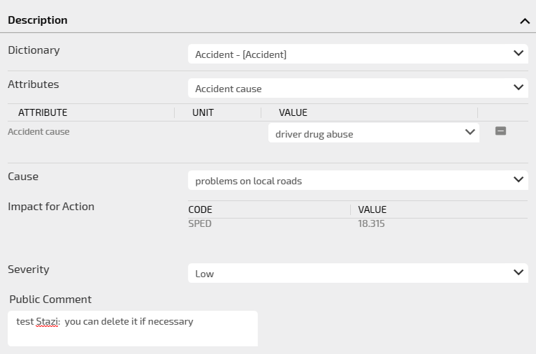
The action can be described by setting several attributes.
|
Option |
Description |
|---|---|
|
Dictionary |
Select the dictionary. Every dictionary is associated with a set of attributes that can be selected and set. An attribute is linked to a specific DATEX II class. |
|
Attributes |
Select the attribute. The selected attribute is listed in the order of selection, from the first to the last. Every attribute is defined by three values:
The attribute set depends on the Dictionary. Only the selected valid attributes are used to calculate the values in the Impact for Action section. |
|
Cause |
Select the cause of the action. |
|
Impact for Action |
All set attributes contribute to compute the impact of the event on the affected streets, therefore setting some parameters like:
Important: After the scenario SAVE, the couple <CODE-VALUE> is set with read-only values. |
|
Severity |
You can select one of the available values. The selected value is cast to a numerical value (range 0 - 1) that affects the priority level for that action. |
|
Public Comment |
You can add a comment to be published. |
The impact of the action (an action can be considered as an "asynchronous event") is based on a set of rules that can be enabled according to the selection of the attributes associated to a specific dictionary (see → DATEX II Interface methodology > Default rules).
Important: On the TS GUI, attributes used to enable rules are classified as Dictionaries. A dictionary identifies a specific event type. The table generally indicates attributes available for all dictionaries. If an attribute belongs to a specific dictionary, it is associated to the indication: (DictionaryName dictionary).
The first (leftmost) column shows the available attributes on the TS Event GUI that must be selected for defining the action and enable the associated rules (indicated in the other two columns).
Important: The table is not an exhaustive collection of ALL applicable impact event rules. Other and different rules may be set, according to specific customizations.
|
Attributes selectables on TS GUI |
Maximum residual speed [km/h] |
Remaining capacity remaining |
|---|---|---|
|
Capacity remaining |
0.80 × LinkOriginalSpeed |
[capacityRemaining] |
|
Number of lanes restricted Original number of lanes |
0.80 × LinkOriginalSpeed |
1 − [numberOfLanesRestricted] / [originalNumberOfLanes] |
|
Number of operational lanes Original number of lanes |
0.80 × LinkOriginalSpeed |
[numberOfOperationalLanes] / [originalNumberOfLanes] |
|
Number of lanes restricted Original number of lanes Traffic constriction type = "lanes partially obstructed" |
0.80 × LinkOriginalSpeed |
1 − 0.5 × [numberOfLanesRestricted] / [originalNumberOfLanes] |
|
Number of operational lanes Original number of lanes Traffic constriction type = "lanes partially obstructed" |
0.80 × LinkOriginalSpeed |
1 − 0.5 × ([originalNumberOfLanes] - [numberOfOperationalLanes]) / [originalNumberOfLanes] |
|
Number of lanes restricted |
0.80 × LinkOriginalSpeed |
1 − [numberOfLanesRestricted] / LinkOriginalNumOfLanes |
|
Number of operational lanes |
0.80 × LinkOriginalSpeed |
[numberOfOperationalLanes] / LinkOriginalNumOfLanes |
|
Number of lanes restricted Traffic constriction type = "lanes partially obstructed" |
0.80 × LinkOriginalSpeed |
1 − 0.5 × [numberOfLanesRestricted] / LinkOriginalNumOfLanes |
|
Original number of lanes Number of operational lanes Traffic constriction type = "lanes partially obstructed" |
0.80 × LinkOriginalSpeed |
1 − 0.5 ×([originalNumberOfLanes] - [numberOfOperationalLanes]) / LinkOriginalNumOfLanes |
|
Traffic constriction type = “carriageway blocked” OR “road blocked” |
LinkOriginalSpeed |
0 |
|
Traffic constriction type = “carriageway partially obstructed” OR “road partially obstructed” |
0.80 × LinkOriginalSpeed |
0.5 |
|
Abnormal traffic type = “stationary traffic” ( Abnormal traffic dictionary) |
0.1 × LinkOriginalSpeed |
Not applicable. |
|
Abnormal traffic type = “queuing traffic” ( Abnormal traffic dictionary) |
0.25 × LinkOriginalSpeed |
Not applicable. |
|
Abnormal traffic type = “slow traffic” ( Abnormal traffic dictionary) |
0.60 × LinkOriginalSpeed |
Not applicable.
|
|
Abnormal traffic type = "heavy traffic” ( Abnormal traffic dictionary) |
0.80 × LinkOriginalSpeed |
Not applicable. |
|
Temporary speed limit < LinkOriginalSpeed ( Speed management dictionary) |
[temporarySpeedLimit] |
Not applicable. |
|
Road or carriageway or lane management type = “carriageway closures” or “closed permanently for the winter” or “overnight closures” or “road closed”. ( Road or carriageway or lane management type dictionary) |
LinkOriginalSpeed |
0 |
|
Original number of lanes Road or carriageway or lane management type = “narrow lanes. ( Road or carriageway or lane management type dictionary) |
0.80 × LinkOriginalSpeed |
([originalNumberOfLanes] − 1) / [originalNumberOfLanes] |
|
Road or carriageway or lane management type = “intermittent short term closures” OR “lane closures” OR “narrow lanes”. ( Road or carriageway or lane management type dictionary) |
0.80 × LinkOriginalSpeed |
0.75 |
|
Road or carriageway or lane management type = “single alternate line traffic”. ( Road or carriageway or lane management type dictionary) |
0.50 × LinkOriginalSpeed |
0.50 |
|
Option |
Description |
|---|---|
|
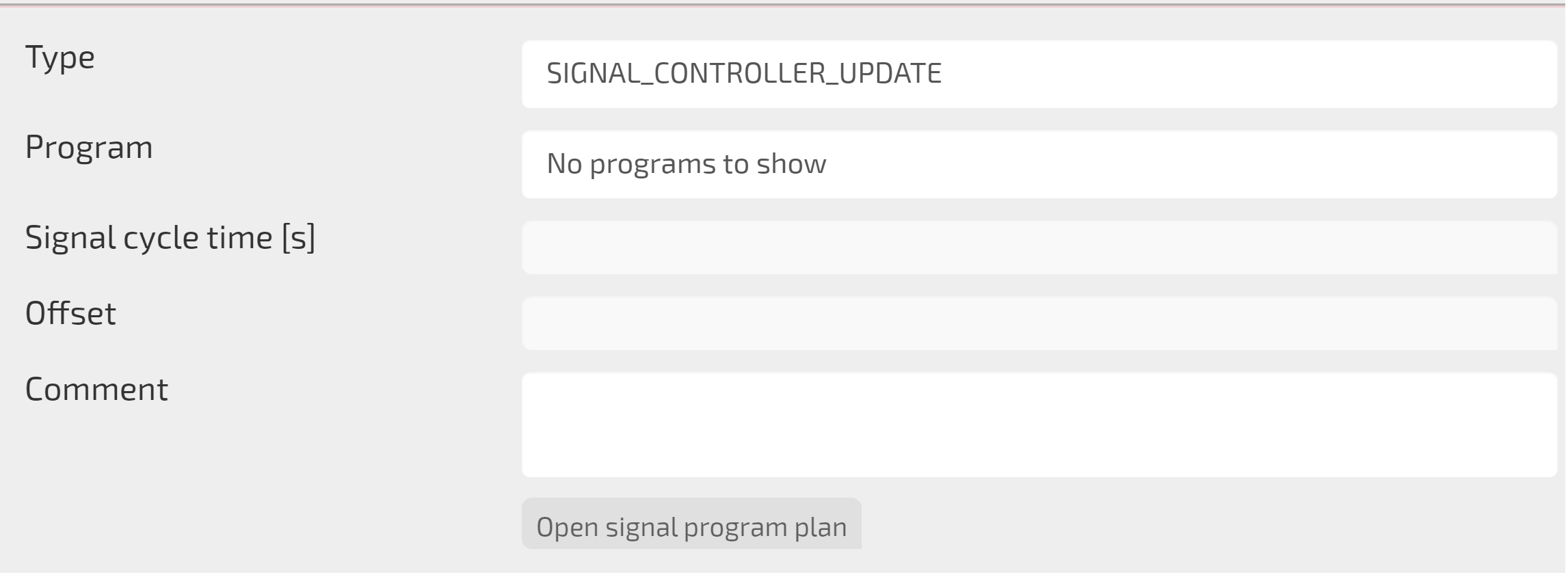
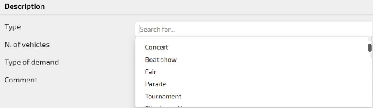
Type |
Type of the program available to set the Signal action. |
|
Program |
The selected signal program. If no signal program is available, the string No program to show appears. |
|
Show dynamic programs |
If the check-box is ticked, only the available dynamic signal programs are listed in the Program area. |
|
Signal cycle time |
It sets the cycle time, measured in [s], of the Program signal program. |
|
Offset |
It sets a number>0, measured in [s], to define the value for managing a delay in starting the selected program. |
|
Comment |
Text field to define a custom text to improve the meaning of the Signal action. |
|
Open signal program plan |
Click it, if enabled, to examine the signal program plan. |
|
Option |
Description |
|---|---|
|
Type |
In the drop-down menu, you can select the type of demand event. |
|
N. of vehicles |
Number of vehicles =>0, involved in the demand event. |
|
Type of demand |
Boolean value to distinguish the traffic direction associated to the demand:
|
|
Comment |
You can add a comment to be published. |
According to the action type chosen, you can manage a varied set of information:
- ROAD
- REROUTING
- SIGNAL
- DEMAND
You can manage different geometric entities:
- Linear, displayed as thick lines with event icons on both terminal points.
- Area, displayed as polygons with an icon in the middle.
- Turn, displayed as a line composed of two different segments.
A rerouting action is basically a road action with a special location, which allows to select:
- A main path.
- A list of alternative paths (routes).
For each path, a compliance must be specified to indicate the percentage of hosted flow. Traffic is re-routed to different paths according to the specified percentage values.
To define a rerouting action, you can see → Setting a signal action.
A signal action is an action to model the behavior of a specific signal.
You can choose the contents of the associated Description section (→ Description section: SIGNAL).
|
Option |
Description |
|---|---|
|
ON MAP |
You can define an action by working directly on the map and defining an area - displayed as polygons with an icon in the middle |
|
BY ATTRIBUTE |
You can select a specific attribute from a list (→ Setting the geometry of an action: BY ATTRIBUTE). |
You can either select a zone from map (using the ON MAP button) or a list of zones (using the BY ATTRIBUTE button).
|
Option |
Description |
|---|---|
|
ON MAP |
You can select zones or centroids directly on the map (→ Setting the geometry of an action: POINT). |
|
BY ATTRIBUTE |
You can select a specific attribute from a list (→ Setting the geometry of an action: BY ATTRIBUTE). |
Scenario operations
Several operations are available for you to manage a scenario.
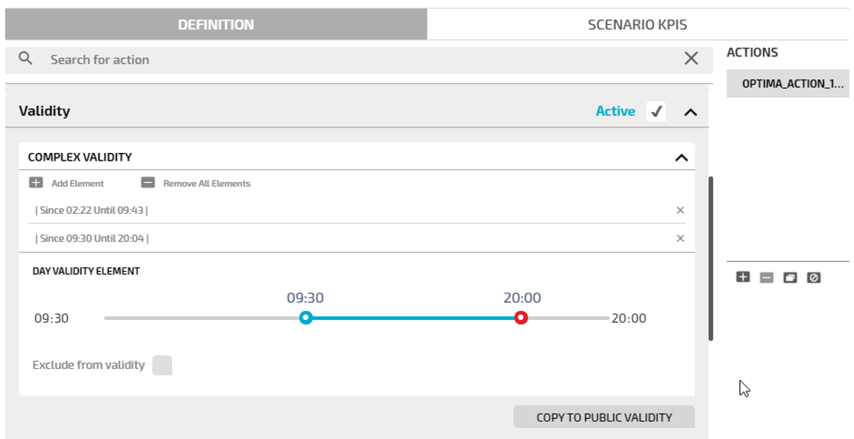
You can define the time period for a day (for example, from 2 AM to 5 AM).
-
On the map, click the event icon.
The Scenario window opens.
-
Click the Complex Validity accordion pane.
The accordion pane opens.
- Click the Add Element icon to define a complex validity setting.
- Select the validity time period through the slide bar.
- Select the Exclude from validity check-box to exclude all complex validity items from validity (by default, they are included).
- Repeat steps 3, 4 and 5 to add a new complex validity set.
- Click COPY TO PUBLIC VALIDITY to export the complex validity settings to the Publication Validity section.
- Click SAVE.
All the configured complex validity sets are listed under the Add Element icon.
You can remove all complex validity time periods you previously set in relation to an action.
-
On the map, click the event icon.
The Scenario window opens.
-
Click the Complex Validity accordion pane.
The accordion pane opens.
- Click the Remove All Elements icon to delete all items listed under the Add Element icon.
- Click SAVE.
All complex validity settings are deleted.
You can unpublish an action.
Tip: An unpublished event can be both active or inactive.
-
On the map, click the action icon.
The Scenario window opens.
-
In the section Publication Validity, deselect the Publishable check-box.
The check-box label turns to Not Publishable and is colored in red.
-
Click SAVE.
An unpublished event is not displayed on Virtual Message Sign (VMS) panels, but is represented on the map.
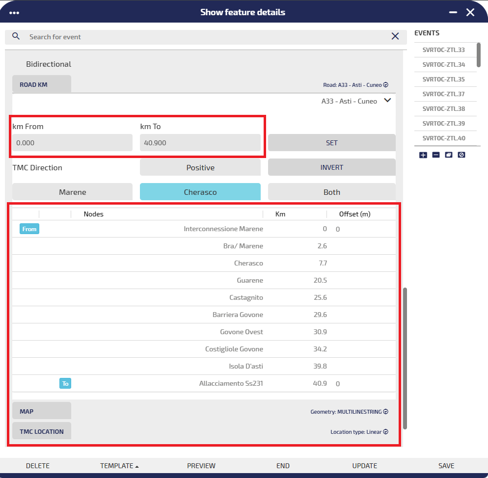
You can set the exact start point and end point of a linear action.
-
On the map, click the action icon.
The Scenario window opens.
-
Click the Location accordion pane.
The accordion pane opens.
-
Click ROAD KM.
The associated pane opens.
-
Select the name of a street from the drop-down list.

-
Click on the label km From to select the start point.
-
Click on the label km To to select the end point.
Tip: You can directly set the kilometric start point and end point in the text boxes, respectively km From and km To, and by next clicking SET.
-
Click SAVE.
You can set different types of action geometries directly on the map and using the mouse.
-
On the map, click the action icon.
The Scenario window opens.
-
Click the Location accordion pane.
The accordion pane opens.
-
Click MAP.
The associated pane opens.
-
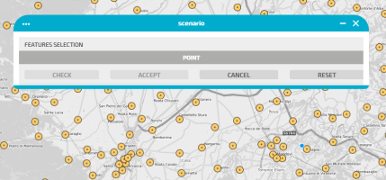
Select the type of action:
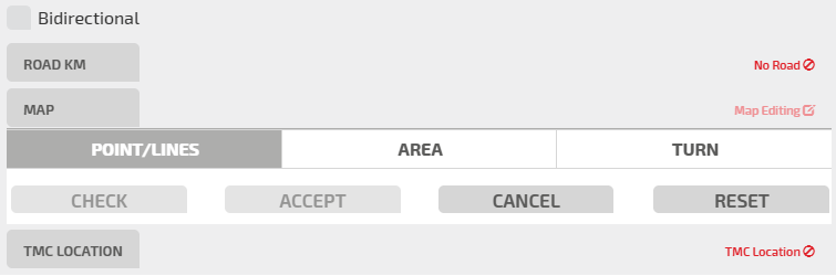
Important: To set an entity, you must click ACCEPT. To undo an accepted action, click RESET.
- Click POINT/LINES.
-
Click on the map and track a linear action (as a sequence of points).
- Click CHECK.
-
Click ACCEPT to confirm the geometry of the event.
-
Click SAVE.
- Click AREA.
-
Use the mouse to define a single polygon on the map:
- Click CHECK.
-
Click ACCEPT to confirm the geometry of the event.
-
Click SAVE.

- Click TURN.
-
Click a point on the map.
-
Click CHECK.
A list displays all the turns associated to the nearest street of the clicked point: select one of them.
-
Click ACCEPT to confirm the geometry of the event.

-
Click SAVE.
Tip: To facilitate the setting of a Turn entity, it is useful to activate the Streets layer.
You can set different types of event geometries directly on the map and using the mouse.
-
On the map, click the action icon.
The Scenario window opens.
-
Click the Location accordion pane.
The accordion pane opens.
-
Click TMC LOCATION.
The associated pane expands.
-
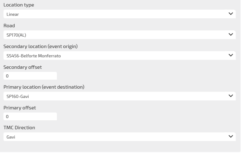
You can geolocate a point, linear, area, or turn action.
-
Set the attributes of the TMC location.

-
Click SAVE.
You can set different types of action geometries directly on the map and using the mouse.
-
On the map, click the action icon.
The Scenario window opens.
-
Click the Location accordion pane.
The accordion pane opens.
-
Click ON MAP.
The POINT associated pane opens.
-
Select one zone (or centroid), represented by the yellow circles on the map, with a left-click:
Important: To set an entity, you must click ACCEPT. To undo an accepted action, click RESET.

You can set different types of event geometries directly on the map and using the mouse.
-
On the map, click the event icon.
The Scenario window opens.
-
Click the Location accordion pane.
The accordion pane opens.
-
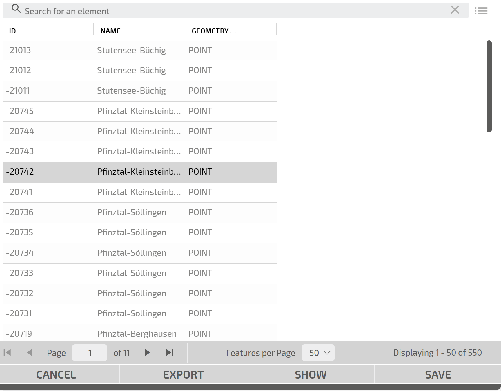
Click BY ATTRIBUTE.
The associated pane opens, listing the attributes associated to the zones indicated on the map (yellow centroids).

- Click SHOW to highlight the zone.
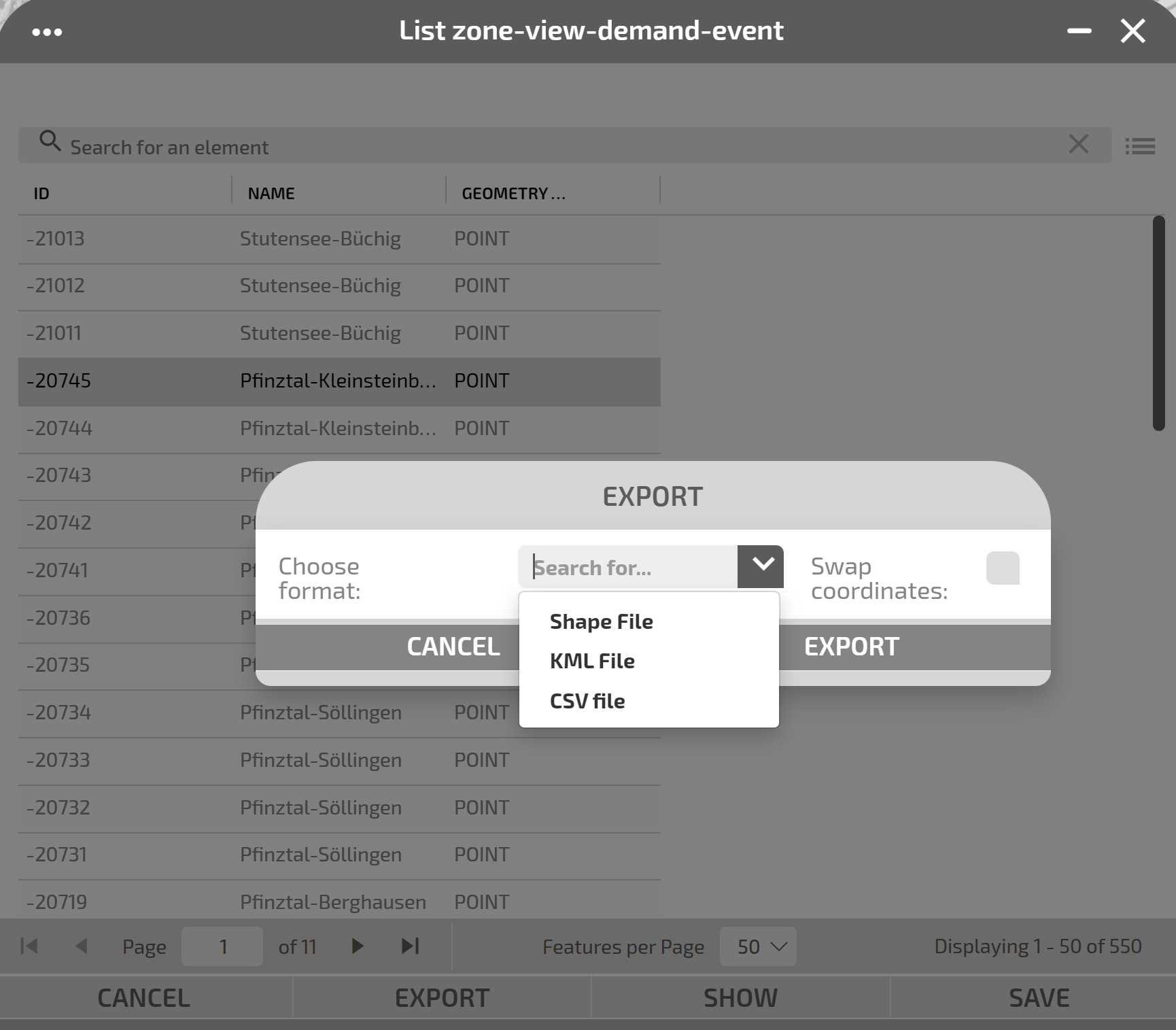
-
Optional: click EXPORT to save the event in three different formats:
- Shape
- KLM
- CSV
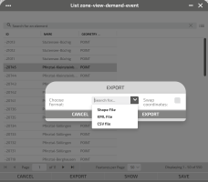
- Click SAVE to save the location.
You can set a rerouting by defining:
- A main path.
- A list of alternative paths (routes).
For each path, a compliance must be specified to indicate the percentage of the hosted flow.
Traffic is rerouted to different paths according to specified percentage values.
-
On the map, click the event icon.
The Scenario window opens.
You can get the same result by clicking the ADD button in the LAYER OPTIONS area.
-
Click the accordion pane REROUTING.
-
Click the Location accordion pane.
The accordion pane opens.
-
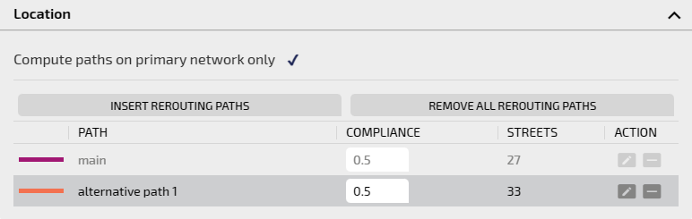
Click INSERT REROUTING PATH.
The Event window is reduced to allow you to make a selection on the map.
-
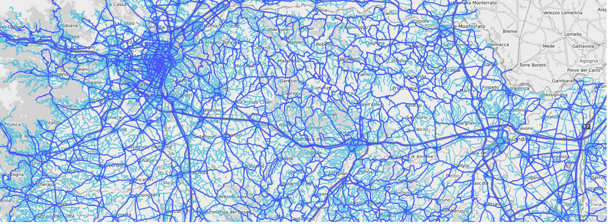
Some automatic actions are performed:
- The primary network (Links layer, dark blue) is activated.
-
The secondary network (Streets layer, light blue) is activated.

Important: The colors of the layers can be set differently.
-
The Main Nodes layer is activated.
Tip: The Main Nodes is a "virtual layer" that is not on the list of available layers. It hosts a logic contraction of some links used to model some network area such as, for example, intersections. All the links belonging to such intersection are modeled as a single “node” in order to simplify the computation of the simulation engine.
Important: The Main Nodes are highlighted during the selection of the rerouting event paths; if a link within a main node is not recognized, a rerouting path can neither start nor end entirely within a main node. In this case, the event geometry would be inconsistent and the computation as well.
-
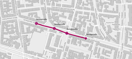
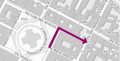
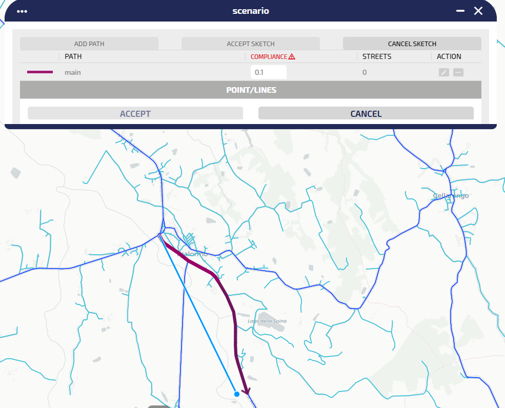
On the map, use the blue pointer to track the main path.
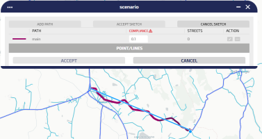
When you click on map one time, the cursor is “followed” by a purple arrow which represents the actual path:

A double left click confirms the path selection.
Tip: You can specify a list of points on the map. Left click one time to set every single point. A double left click sets the final point.

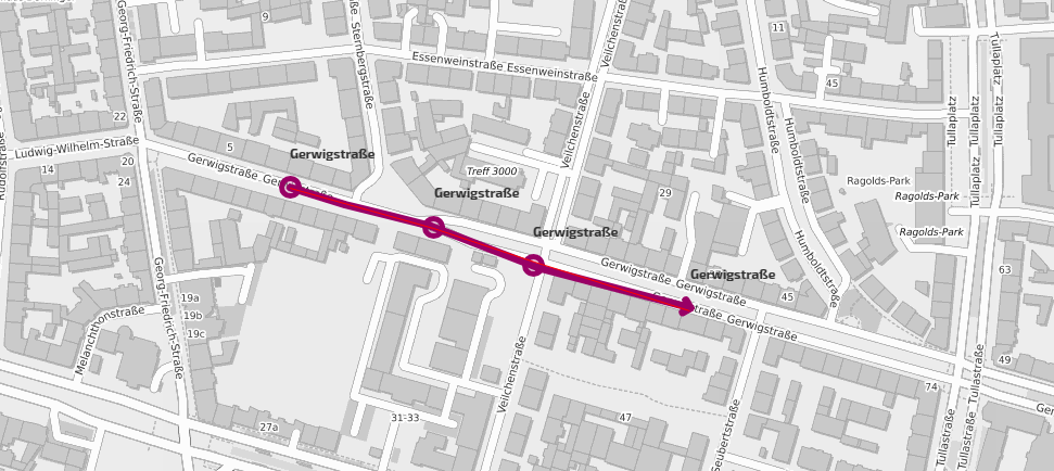
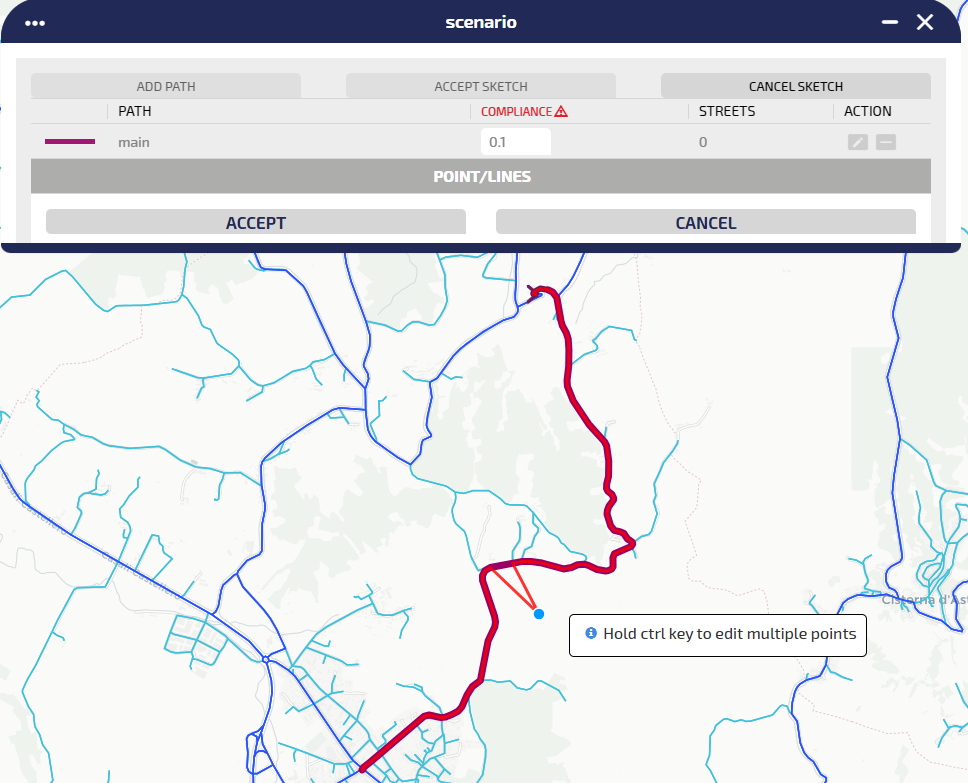
-
A red line is tracked and you can now edit the path you just created by simply clicking on the path itself and dragging the points:
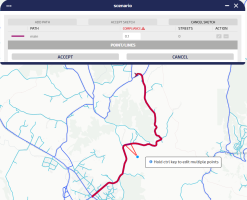
Tip: You can edit multiple points by simply holding the CTRL key. When the key is released, the path is recomputed and updated on the map.
-
Click ACCEPT to validate the tracked main path.
-
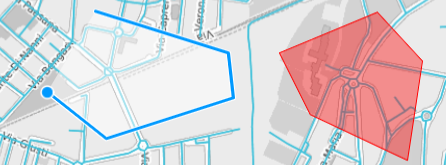
The alternative path definition is automatically activated.
By just moving the mouse around the map window, the alternative path is automatically computed, trying to connect:
- The starting path segment of the main path (which must be the same for all the alternatives).
- The current mouse position.
- The last path segment of the main path (which must be the same for all the alternatives).
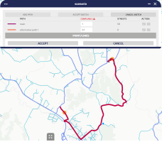
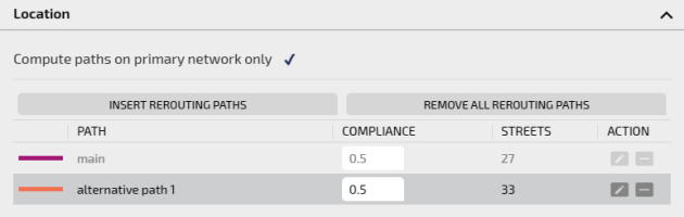
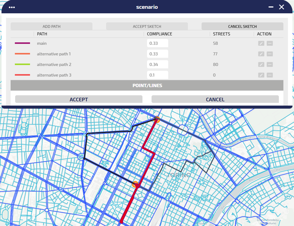
The main path is shown as a black line, while the new path “alternative path 1” is drawn in purple.
Tip: The start and the last path segment are indicated by an orange circle. A pop-up appears if the user hovers with the mouse on such circles.

-
Double click on the map to confirm the map selection (as for the main path).
-
Set the compliance of the path tracked at step 10 by selecting a value in COMPLIANCE.

Tip: The compliance of a path represents the probability of the flow rerouting on that path. The compliance values are automatically adjusted as a fair split 1/N, where N is the number of defined paths. You can change the values, considering that the sum of these N values MUST BE 1.
-
Click ACCEPT to confirm the tracked path.
If the current compliance sum is different from 1, it is automatically updated.
-
Click ADD-PATH for (N-1) times, hence repeating the steps from 10 to 13, to add (N-1) rerouting paths.
Tip: The rerouting paths are limited by the orange nodes.
-
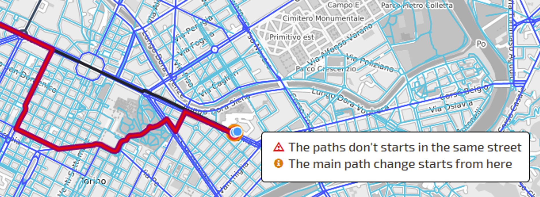
The already-defined alternatives are all shown in gray scale colors. If the returned path doesn't include either the start or end segment corresponding to their position on the main path, the entire event is inconsistent.
The system shows:
- A red triangle icon closes the STREETS label
- A value of STREETS= 0 is associated with the wrong alternative path (in the example, the alternative path 2)

A mouse hover interaction shows the reason of the error:

-
Starting from the paths set that define the rerouting event, you can make two specific actions on a single selected path:
- Click on
 to update the path.
 - Click on
 to remove the path.
- Click on
-
Click ACCEPT SKETCH to accept the current configuration (without errors) and exit from map selection mode.
-
Click CANCEL SKETCH to exit from map selection mode.
Important: If the tracked path is not accepted, the entire rerouting sketch is canceled.
-
Click SAVE to enable the rerouting event you just set.
Important: The SAVE button is enabled only if the sum of the compliances of the listed paths is 1.
On the map, the new rerouting event is shown through its icon:


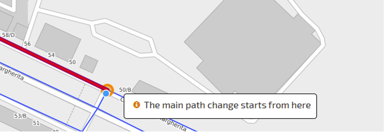
Tip: Considering the featured street details featured, if the street belongs to the main path, you can open the SHOW RELATED LINK DETAILS (RED rectangle).
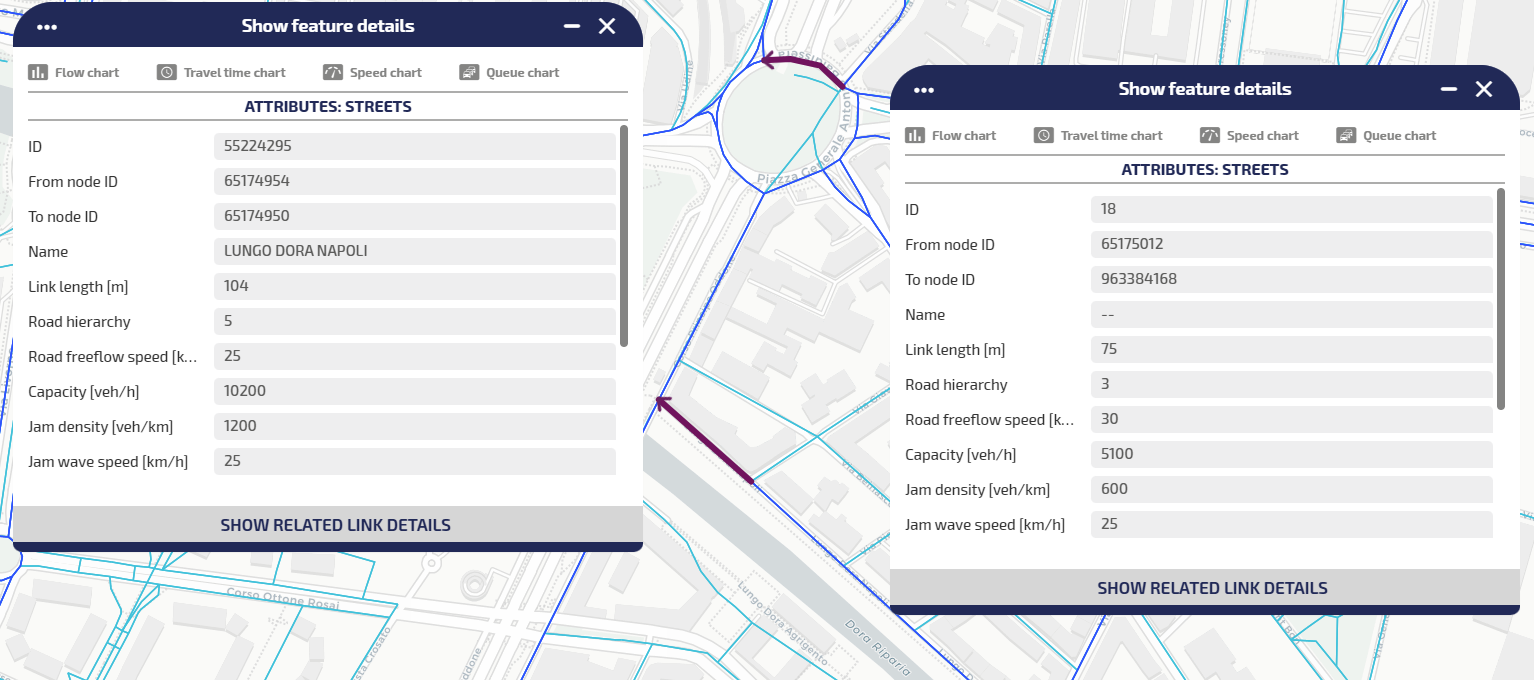
In the image on the left, as for the street detail related to street ID=55228044, it is not belonging to a main path: therefore the button SHOW RELATED LINK DETAILS is not selectable.
On the right, as for street ID=55228419, you can access details of the link.
-
On the map, click the action icon.
The Scenario window opens.
You can get the same result by clicking the ADD button in the LAYER OPTIONS area.
-
Click the SIGNAL accordion pane.
-
Click the Location accordion pane.
The accordion pane opens.
-
Select one of the available options:
- ON MAP: select an area (→ Scenario management > AREA).
- BY ATTRIBUTE: select an available attribute from the list.
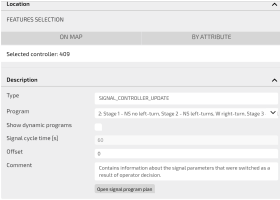
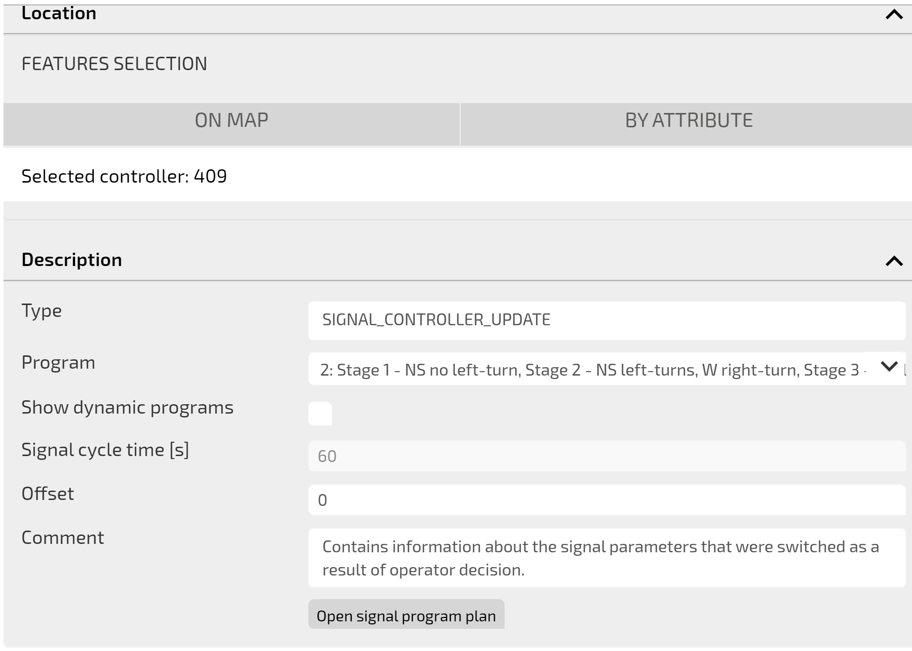
-
According with the previous step, the Description accordion panes opens, and several fields are automatically set (→ Description section: SIGNAL):
In the bottom Button Bar you can select different operations. Every operation affects the whole set of attributes you previously set in the GUI.
You can delete a scenario displayed on the map that hosts an active instance of the Scenarios layer.
-
On the map, click the scenario icon.
The Scenario window opens.
-
Click DELETE.
A pop-up window opens.
- Click OK to confirm the deletion.
The icon of the scenario is deleted from the map.
You can save a template based on an scenario configuration. A template represents a repeatable "model" for the definition of similar scenarios. Saved templates can be loaded to speed up the configuration of a new scenario.
-
On the map, click the event icon.
The Event window opens.
-
Open one or more sections and set the attributes of the event.
A pop-up window opens
-
Click Save Template to save the current attributes as a template that can be retrieved and updated.
Important: You can save different templates with the same name (templates are associated with different internal identifiers), but this is not considered a best practice.
You can load a saved template.
-
On the map, click the scenario icon.
The Scenario window opens.
-
Click TEMPLATE > Load template to load a stored template.
You can select one template from the list of available templates.
-
Click the Load icon to load it in the related template.
The Scenario GUI is set with the attributes of the loaded template.
The preview of a scenario provides a short description of the scenario.
-
On the map, click the scenario icon.
The Scenario window opens.
-
ClickPREVIEW.
A pop-up window opens and displays some base information which is associated with the scenario.
You can update only the update time that is associated with the event. The update time can be used by external agents for their purposes.
-
On the map, click the event icon.
The Event window opens.
-
Click UPDATE.
A pop-up window opens and confirms the success of the operation.
Tip: When you save an event, you update ALL the information associated with the event.
You can access the SCENARIO workspace to manage simulations groups.
-
On the map, click the scenario icon.
The Scenario window opens.
-
Click EVALUATE.
The REAL TIME SCENARIO pop-up window opens (see → Scenario workspace).
You can update an event displayed on the map that hosts an active instance of the Events layer.
-
On the map, click the event icon.
The Event window opens.
-
Open one or more sections and set the attributes of the event.
- Click SAVE to confirm all settings.
All data set in the Event window are saved.
Tip: It is mandatory to set some attributes. If the mandatory attributes are not set, they are indicated in red and marked with a warning sign. In this condition, the event cannot be saved.