1. In the Network editor window, click the  Insert mode icon.
2. In the Network editor window, click the Main zones button.
3. In the network, click the position where you want to insert the centroid of the main zone.
|
Tip: You specify settings for the newly inserted network object directly in the Quick view (Main zones) window. The attributes of main zones are described here (Properties and options of main zones). If you want to display the Create main zone window when inserting the object, you can right-click the Main zones button in the Network window and activate Show dialogs when inserting objects. |
The centroid of the main zone is inserted. You can now insert a border and thus allocate the partial zones (all zones with a centroid within the border). The border is optional. It defines the partial zones and determines the surface of the main zone i.e. illustrates its extent.
You can now proceed as follows:
- If you do not want to allocate partial zones to the main node, press the Esc key. The main zone is then inserted as centroid without a border. You can define the border and allocate the partial zones later (Creating a boundary).
- If you want to allocate partial zones to the main zone, proceed with the next step.
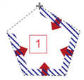
4. Specify the border of the main zone by inserting at least three polygon points in a counterclockwise direction in the desired positions.
The edges of the border polygon are displayed as a rubber band. The hatching and the arrows indicate the direction of the face (Fundamentals: The surface data model in Visum).
5. To confirm the definition of the border, press Enter.
The border is created. The partial zones which lie within the border are allocated to the main zone and the main zones is inserted in the network.
|
Note: You can change the border afterwards (Shifting polygon points). |
