For the illustration of roads and other transport-related areas, which are more or less structured by central reservation or traffic islands, there are several possibilities of displaying these in a transport model. For relatively strong abstraction, the correlation of components with regard to content, for example lanes of both directions on a road are illustrated by an individual link. This is the best view for traffic engineering analyses. With the increasing application of navigation networks with disaggregated illustrations of reality as a basis for transportation models, networks divided into small sections play an increasing role. These models then have both lane directions as two separated links in the Visum model. However, combining these in an aggregated display would create a lot of work as well as a loss of information, because the existing refined distribution is required when carrying out micro-simulations with the micro-simulation program Vissim.
For conventional modeling, there is a contradiction between the activated demand for disaggregated network display and that of differentiated turn delays per turn type. We want to make it clear using an example.
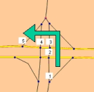
Image 12: Intersection area with multiple nodes
If two roads intersect as in Image 12 with separated lanes, the intersection area splits up into four nodes. If a triangle island is also present, the turns with the respective node are also added. A road user who comes from the bottom of the image and turns left, successively passes nodes 1 to 5. Only at node 3 he follows a turn, which constitutes a left turn; all other nodes he passes straight. Right turns only meet two nodes, at both nodes they traverse a turn to the right, whereas straight paths pass four nodes. If turn penalties were assigned, the sum of all traversed turns effects the node, although the contained shares, such as waiting at a signal controller only once has an effect in reality. A possible solution could be, to individually set the turn times of each movement, so that the sum of all traversing turns results in the desired value for the movement. This, however, is not possible with a type-based allocation of values, because turns of the same type would have to be attributed differently at the same node. There should rather be a linear equation system for each intersection area.
The main node puts the thought underlying such a solution into effect by incorporating the nodes belonging to an intersection area explicitly in a separate object. All nodes of the intersection area thus form a logic unit, which takes the place of the previous nodes. Turns are regarded on the logic level of the main node and are called main turns here.
Links whose From node and To node belong to the same main node are called inner links of the main node. It is called a cordon link if only one of the nodes is part of the main node. These constitute the access to and egress of main node: Each OD pair accesses the main node via a cordon link and egresses it via another one. A link is also a cordon link if both nodes are allocated to different main nodes.
The combination of several nodes in a main node defines, based on the nodes of the main nodes, different kinds of links:
- Inner links: From node and To node belong to the main node (Image 13: (1)).
- Cordon links: one of the two nodes belongs to the main node, the other one lies outside of it (Image 13: (2)).
- Directed links or One-way streets: this is a link with at least one direction with an empty TSys set or zero lanes.
There is also cohesion between main nodes and different node types:
- Inner nodes: only inner links originate here (Image 13: (3)).
- Cordon nodes at least one cordon link originates here, additionally possibly inner links (Image 13: (4)).
- Partial nodes:any nodes that are allocated to a main node. These could be inner nodes, cordon nodes, and nodes lying beyond the boundary of the main node.
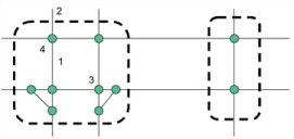
Image 13: Node and link types of main nodes
|
Note: Main node polygons are managed like surfaces and can be made up of multi-face polygons or polygons with "holes" (Multi-part surfaces). |
