A surface can be made up of several faces (multi-part surfaces). Generally, a multi-part surface is defined by a set of so-called faces. Each face is a polygon with a sign. This is positive if coordinates encircle the polygon anti-clockwise and negative if the coordinate sequence is clockwise. Positive faces are thus digitalized anticlockwise, negative faces clockwise. This way, the type of polygon is clearly defined when interactively modifying polygons in the network display. This orientation of a face is thus a significant object feature. Positive faces add to the surface, negative surfaces subtract from it (holes).

Image 44: Positive and negative surfaces
Visum automatically normalizes the definition of any surface it encounters. Faces never intersect and a positive face will always (directly) contain only negative faces and vice versa.
What is a normalized surface and why does it need to be normalized?
Running geometrical operations (like Intersect or Territory indicators) efficiently on complex surfaces requires the use of a normalized representation. The Table 38 shows some examples for the normalization of surfaces.
|
|
Specified surface |
Normalized shape of the surface |
|
1 |
Two separate faces |
OK – the surface remains unchanged |
|
2 |
Two overlapping faces |
not OK – both faces have been merged |
|
3 |
A face with a hole |
OK – the surface remains unchanged |
|
4 |
A face with a hole which intersects the boundary of the surface |
not OK – the hole is omitted and the face adjusted |
|
5 |
A face with an intersecting boundary |
not OK – the negative part is deleted |
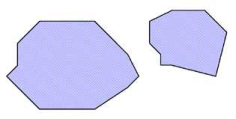


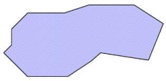

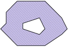


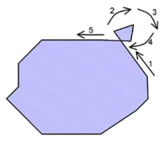

Table 38: Examples of the normalization of surfaces
A surface is thus "normalized“ if the following conditions are met:
- None of the faces of the same orientation overlap. This means
- all positive faces are separated (criterion 1a).
- none of the negative faces intersect nor touch the open plane (criterion 1b).
- none of the faces have intersecting boundaries (criterion 2).
The simple example of the area calculation suffices to understand why a normalized representation facilitates geometrical operations. The area of normalized surfaces results directly from the sum of the areas of its faces. The sign depends directly on the orientation. Without normalization, the areas of all occurring intersections of the faces would have to be subtracted from the result. This would imply a significant increase in computation time. Computation time particularly increases because the mere determination of the intersection of sets with multiple overlaps is a complex algorithmic procedure.
When does the program normalize?
Normalized surfaces are a prerequisite for efficient use of polygons in various geometric calculation procedures. This is why this normalization is automatically performed during interactive editing of polygons. The examples above show surfaces that can be inserted interactively just as they are displayed in the left column. However, when you are done with inserting, Visum automatically normalizes the surfaces. When loading surfaces from network or shape files, it is checked whether they are normalized or not. If required, the input data is then normalized. If polygons have already been normalized or the data is not required for geometrical calculation procedures (e.g. POI layers that merely serve as a background), you can optionally leave out the normalization check and so reduce import time.
|
Note: However, if non-normalized surfaces that were originally only meant for background display are later on used in calculation procedures, this can lead to erroneous results, as normalization is required for such operations. If you are not sure whether a surface has been normalized or not, make sure you normalize it, if required (User Manual: Normalizing all surfaces). |
How accurate is the normalization (for experts)?
The order in which the faces of a surface are defined is crucial to the normalization. In the network file, this order is defined by table Surface items.
The polygon of a face needs to be preprocessed if its boundary intersects (see Table 38, example 5). In this case, the face is split into non-intersected segments. This segmentation is done in such a way that the components do not intersect either. The orientations of the segments do not change, i.e. a scroll like the one in Table 38, example 5 is interpreted as a negative face. The positive and the negative polygons determined in this way are merged with the intermediate result of the faces considered before. If no boundaries intersect, segmentation is not necessary. The specified polygon and the intermediate result of the faces considered before can be merged directly.
During this aggregation, faces sometimes have to be merged. This is, for example, the case in Table 38, example 2, where two positive faces are merged. It can however also happen if faces are omitted and other faces change their shape. This is, for example, the case in Table 38, example 4.
This approach particularly implies that the first face must not have a negative orientation. Should this be the case, criterion 1 b) immediately takes effect, i.e. the face is dismissed.
The question whether the orientation of the polygon of a face matches the enclave attribute of its surface item needs special attention. Here, information might be inconsistent when reading networks. In this case, the enclave feature wins, i.e. the orientation of the polygon is inverted where required. The advantage of this rule is that by editing just one attribute in the network file, a positive polygon face can be turned into a negative one and vice versa.
