|
Notes: For the description of this control type, please refer to HCM 2000, chapter 17. In HCM 2010, refer to chapter 19 and in HCM 6th Edition In Visum, two-way nodes are modeled by the control types two-way stop and two-way yield. In the HCM, the description refers to two-way stop nodes. Basically, the computation is the same. The only difference is the calculation of wait times in Step 8. Nodes of the signalized control type are also calculated according to the method for yield-controlled nodes if no signal controller has been allocated or the signal controller has been turned off. |
The two-way stop analysis method is based on the gap acceptance theory. The basic idea is to calculate potential capacities for all movements, and then subtract capacity from these movements based on movement rank (priority). The calculation flow chart looks similar to Image 75.
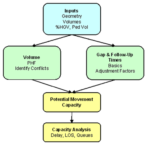
Image 75: Method of calculation at two-way stops
If you use the HCM 2000 operations model for two-way stop nodes, the Visum attributes in Table 102 will show effect. Make sure that they are set to realistic values prior to running the analysis.
|
Network objects |
Attribute |
Description / Effect |
|
Link |
Slope |
Used in Step 3 |
|
Node |
ICA peak hour factor volume adjustment |
Factor for the initial volume adjustment to peak volume; volumes are divided by both node and turn adjustment factors |
|
Geometry |
All |
Geometry data of lanes, lane turns and crosswalks |
|
Turns |
Share of HGV |
HGV share is used in Step 3 + Step 4. Fixed value that applies for turns. |
|
Turn |
ICA peak hour factor volume adjustment |
Factor for the initial volume adjustment to peak volume; volumes are divided by both node and turn adjustment factors |
|
Turn |
ICA Preset critical gap |
Critical gap value of your choice |
|
Turn |
ICA Use preset critical gap |
Optionally, you can overwrite the critical gap used in Step 3. Activate this option, to use the value set under ICA Preset critical gap. |
|
Turn |
ICA Preset follow-up time |
Follow-up time value of your choice |
|
Turn |
ICA Use preset follow-up time |
Optionally, you can overwrite the follow-up time used in step Step 4 Activate this option, to use the follow-up time set. |
|
Turn |
ICA Preset critical gap stage 1 |
This attribute takes effect on subordinate traffic flows together with the attributes ICA Use two stage gap acceptance (leg) and ICA Use preset critical gap (turns). The value entered replaces the critical gap default value in Phase 1 of the HCM, when the so-called "2-stage gap acceptance" method is applied. |
|
Turn |
ICA Preset critical gap stage 2 |
This attribute takes effect on subordinate traffic flows together with the attributes Use two stage gap acceptance (leg) and Use preset critical gap (turns). The value entered replaces the critical gap default value in Phase 2 of the HCM, when the so-called "2-stage gap acceptance" method is applied. |
|
Leg |
Is Channelized |
There is a separate right turn |
|
Leg |
Channelized Control |
This attribute takes effect in conjunction with the attribute Is Channelized in Step 2 and in accordance with the regulations specified in the HCM. |
|
Leg |
ICA Compute flared lane effects |
This attribute takes effect in conjunction with the attribute ICA Flared storage size and according to the HCM formulas for shared lane capacity calculation. |
|
Leg |
ICA Flared storage size |
According to the HCM formulas, the flared storage size in number of vehicles takes effect during shared lane capacity calculation. |
|
Leg |
ICA Use two stage gap acceptance |
This attribute takes effect in conjunction with the attribute ICA Number of storage spaces in median refuge area, when the so-called "2-stage gap acceptance" method is applied according to the formulas of the HCM. |
|
Leg |
ICA Number of storage spaces in median refuge area |
This attribute defines the number of spaces in the median refuge area and takes effect when the so-called "2-stage gap acceptance" method is applied according to the HCM formulas. |
|
Lane |
ICA Preset critical gap |
Critical gap value of your choice |
|
Lane |
ICA Use preset critical gap |
Optionally, you can overwrite the critical gap used in step Step 3. The analogous value of the turn is not used. Activate this option, to use the critical gap set. |
|
Lane |
ICA Preset follow-up time |
Follow-up time value of your choice |
|
Lane |
ICA Use preset follow-up time |
Optionally, you can overwrite the follow-up time used in step Step 4. The analogous value of the turn is not used. Activate this option, to use the follow-up time set. |
Table 102: Input attributes for the calculation of two-way stops
Output is available through the same attributes as for signalized nodes (Table 101). Additionally, the calculated critical gap and follow-up time data is provided.
The method works with movements (Left, Through and Right) at each approach. Each movement is ranked according to Table 103.
|
Rank |
|
|
1 |
Major Through Major Right Pedestrian passage minor flow |
|
2 |
Major Left Minor Right Pedestrian passage major flow Major Left – priority to gaps in the opposing flow Minor Right – priority to gaps in the flow of the right-most lane of the major flow Pedestrians – Priority to any other flow |
|
3 |
Minor Through |
|
4 |
Minor Left |
|
Note: HCM 2010 also regards U-turns on major flows. They are given rank 2. If the calculation is based on HCM 2010, the U-turn related setting in the procedure parameters will not affect these U-turns. |
Step 1: Flow rate (volumes) calculation for each movement
The 15 min peak flow rates (as calculated from the PHF adjustment) are used as the adjusted movement volumes.
Step 2: Conflicting flows for each movement
In addition to calculating the volumes for each movement, the conflicting volumes for each movement for each approach must be calculated.
|
Notes: Rank 1 movements do not have conflicting flows since they have the highest priority. Mainly, rank 1 movements are excluded from the analysis, with the exception of one additional evaluation (Calculation of the critical vol/cap ratio for the entire intersection). According to HCM 2010, pocket lanes for left turns (rights for left-hand traffic accordingly) in the major flow are dealt with separately. Only nodes with three or four legs are described in the HCM. In Visum, also multi-leg nodes can be calculated. The 'Uncontrolled' rule is applied to conflicting flows between minor legs which are not separated by a major leg. For left-hand traffic, the right-hand calculation is performed symmetrically. |
For right-hand traffic, the following example models the conflict flow of a left turn on a major flow:
- Volume through traffic in opposing direction + volume right turns in opposing direction (does not apply if right turns in opposing direction are separated by a channelized turn and need to attend a yield sign or a stop sign) + pedestrian volumes minor flow crossing
Table 104 shows the equations for conflicting volumes.
|
Movement |
Conflicting flows |
|
Major Left |
OT + OR* + ToP |
|
Minor Right |
JT/N + 0.5JR* + FrP + ToP |
|
Minor Through |
2JL + JT + 0.5JR* + FrP + ToP + 2JLF + JTF + JRF* |
where
|
O |
Opposite direction |
|
T |
Through |
|
R |
Right |
|
L |
Left |
|
N |
Number of through lanes |
|
J |
Major… |
|
I |
Minor… |
|
F |
Far (for minor through/left turns the second major flow encountered) |
|
ToP |
Approach (to) with pedestrian crosswalk |
|
FrP |
Exit (from) with pedestrian crosswalk |
There is a number of cases where the conflicting volume is adjusted:
- If the major flow (right) is separated by a channelized turn and needs to attend a yield sign or a stop sign then this flow will not be considered in the conflicting volume calculation for other flows..
- If the major flow has more than one lane, only the right lane volume of the major flow (= vol / num through lanes) applies as conflicting, for minor right and minor left turns.
- If the major flow has a right turn lane, then the right turns of the major flow do not count for the conflicting volume.
- For left turns from the minor flow, the right turn volume of the opposing direction does not count for the conflicting flow if the destination link of the two turns has more than one lane.
|
Notes: Apart from the U-turns, the HCM 2010 differs from HCM 2000 in subtle differences. For the determination of conflicting flows, please refer to HCM 2010, pages 19-9 to 19-14. The HCM does not regard bending two-way stop/yield cases. In this case, conflicting flows are determined according to Brilon and Weinert, 2002. |
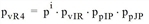
Step 3: Critical gap calculation for each movement
The critical gap is the time an average driver would accept in order to merge with traffic.
Example
Sarah needs 4 seconds of space between vehicles to make her left turn and merge with other traffic safely.
The critical gap equation is:
tcx = tcb + (tcHVPHV) + (tcGG) - tcT - t3LT
where
|
tcx |
critical gap for movement x |
|
tcb |
base critical gap (see Table 105) |
|
tcHVPHV |
adjustment factor for heavy vehicles • percent heavy vehicles |
|
tcGG |
adjustment factor for grade • grade (as a decimal) |
|
tcT |
two stage adjustment factor (currently set to 0 for one stage modeling) |
|
t3LT |
Critical gap adjustment factor for geometry |
The other adjustment factors are:
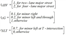
The base values for the critical gap are calculated as shown in Table 105.
|
Movement |
Base critical gap value tcb |
|
|
|
< 4 lanes major flow |
4 + lanes major flow |
|
Major Left |
4.1 |
4.1 |
|
Minor Right |
6.2 |
6.9 |
|
Minor Through |
6.5 |
6.5 |
|
Minor Left |
7.1 |
7.5 |
If the calculated values differ from the observed values, manually set values per turn can be used.
Step 4: Follow-up time calculation for each movement
The follow-up time is the extra time needed for a second car to also take the gap.
Example
Let's assume that Frank would be waiting behind Sarah at the intersection. If he turned just behind Sarah, he would need a follow-up gap of only 2 seconds instead of another 4 seconds to safely merge back into traffic. That is, if the gap between the vehicles was at least 6 seconds long, both Sarah and Frank could turn safely.
The follow-up time equation is:

where
|
tfx |
follow-up time for movement x |
|
tfb |
base follow-up time (Table 106) |
|
tfHVPHV |
follow-up time adjustment factor for heavy vehicles • percent heavy vehicles |
The other adjustment factors are:
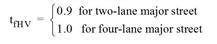
Follow-up times are calculated according tor Table 106.
|
Movement |
Base follow-up time value tfb |
|
Major Left |
2.2 |
|
Minor Right |
3.3 |
|
Minor Through |
4.0 |
|
Minor Left |
3.5 |
If the calculated values differ from the observed values, manually set values per turn can be used.
Step 5: Calculate the potential (or ideal) capacity for each movement
The potential capacity is the capacity which is achieved if this movement uses all potential gaps (i.e. no higher ranking movements take up the gaps). Furthermore, it is assumed that each movement is made from an exclusive lane. The potential capacity is defined as follows:
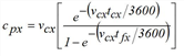
with
|
cpx |
potential capacity for movement x (veh/hr) |
|
vcx |
conflicting flow for movement x (conflict/hr) |
|
tcx |
critical gap for movement x |
|
tfx |
follow-up time for movement x |
Step 6: Calculate movement capacity taking into account impedance effects
Higher ranking movements impede lower ranking movements’ capacities since vehicles making higher ranked turns can use the available gap space before the lower ranked movements. Therefore, we adjust the potential capacity by an adjustment factor to yield the movement capacity. The movement capacity equation is as follows:

where
|
cmx |
movement capacity for movement x (veh/hr) |
|
cpx |
potential capacity for movement x (veh/hr) |
 = probability impeding vehicle movement i is not blocking subject movement
 = probability impeding ped movement j is not blocking subject movement
|
vi |
volume movement i |
|
vj |
volume pedestrian flow j (peds/hr) |
|
w |
lane width (ft), default value 12 ft |
|
SP |
pedestrian walking speed (ft/s), default value is 4 ft/s |
Since the calculation depends on higher rank movement capacities the calculation proceeds from the top down (from rank 1 to rank 4 movements). Impeding vehicle and pedestrian movements for each subject movement are listed in Table 107 aufgelistet.
|
Movement |
Rank |
Impeding movements |
|
Major Through |
1 |
None |
|
Major Right |
1 |
None |
|
Major Left |
2 |
ToP |
|
Minor Right |
2 |
FrP, ToP |
|
Minor Through |
3 |
JL, JLF, FrP, ToP |
|
Minor Left |
4 |
JL, JLF, OT, OR, FrP, ToP |
where
|
J |
Major… |
|
I |
Minor… |
|
O |
Opposite direction |
|
T |
Through |
|
R |
Right |
|
L |
Left |
|
F |
Far (for minor through/left turns the second major flow encountered) |
|
ToP |
Approach (to) with pedestrian crosswalk |
|
FrP |
Exit (from) with pedestrian crosswalk |
Step 6a: Calculate adjustment for impeding major left turns
There is also an adjustment factor for major left if it does not operate from an exclusive lane. The equation uses a default saturation flow rate. It is as follows:
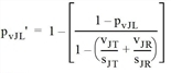
where
|
pvJL‘ |
modified probability of impeding maJor left |
|
pvJL |
unmodified probability of impeding maJor left |
|
vJT |
volume major through |
|
vJR |
volume major right (0 if exclusive right turn lane) |
|
sJT |
sat flow major through (1700 default) |
|
sJR |
sat flow major right (1700 default) |
|
Note: Please refer to HCM 2010 pages 19-20, for the description of a short pocket lane on the major flow scenario. |
Step 6a: Calculate adjustment for minor left turns
In addition, there is a special adjustment for minor lefts (rank 4). The equation is below. Basically the major lefts and the minor through is precalculated and then adjusted. The adjusted value is then used in conjunction with the remaining minor right and pedestrian probabilities.

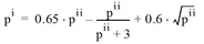
where
|
pvJL |
probability of impeding maJor left near |
|
pvJLF |
probability of impeding maJor left far |
|
pvIT |
probability of impeding minor through |
|
pvR4 |
probability minor left (rank 4) |
|
pvIR |
probability minor right (rank 2) |
|
ppIP |
probability minor pedestrian |
|
ppJP |
probability major pedestrian |
Step 7: Capacities for movements that share lanes
The calculations so far assume that each minor movement operates out of an exclusive lane. When there is a shared lane, a combined capacity is calculated for those movements which share a lane.

where
|
CSH |
shared lane capacity |
|
vi |
volume minor street movement i |
|
cm |
movement capacity minor street movement i |
|
Note: Note that the upstream signal and platoon flow adjustments are currently omitted from the calculation. The same applies for the two-stage gap acceptable adjustment, as well as for the flared approach adjustment. |
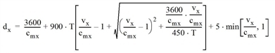
The calculation of control delay is defined as follows:

where
|
dx |
mean delay per vehicle for movement x |
|
cmx |
capacity for movement (shared lane x, CSH) |
|
T |
duration of analysis period (hr) (default 0.25 for 15 min) |
|
vx |
movement volume (shared lane x, VSH) |
A similar formula is used for the calculation of either two-way control type (yield or stop):
Control delay per movement is aggregated to approach with a weighted (by volume) mean of all approach movements / shared lanes. Mean approach delay is then aggregated to the entire intersection with a weighted mean as well. The equations are the same as the ones for signalized intersections.
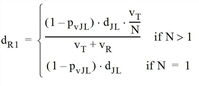
Note that rank 1 movements get no delay. If, however, there is no exclusive left turn pocket, then rank 1 movements may experience delay. There is therefore, an additional delay equation for rank 1 movements when there are no left turns pockets on the major approaches. The equation is as follows:
where
|
dR1 |
delay rank 1 vehicles (s/veh) |
|
N |
number of through lanes per direction of the major flow |
|
pvJL |
probability for an adjustment factor impeding major left [5] |
|
dJL |
delay to major left (s/veh) |
|
vT |
shared through lane volume (for multilane sites, only the volume in the shared lane) |
|
vR |
shared right turn lane volume (for multilane sites, only the volume in the shared lane) |
This delay is then substituted by the zero delay of rank 1 movements when calculating approach and/or intersection delay.
Level of Service is then simply defined as displayed in Table 108 based on intersection delay.
|
LOS |
Mean delay/vehicle |
|
A |
0 – 10 sec. |
|
B |
10 – 15 sec. |
|
C |
15 – 25 sec. |
|
D |
25 – 35 sec. |
|
E |
35 – 50 sec. |
|
F |
50+ sec. |
|
Note: For LOS analyses, HCM 2010 additionally takes into consideration whether the capacity was exceeded. If this is the case, always level F of service will be allocated (HCM 2010, page 19-2). |
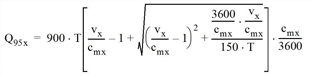
The intersection queue length calculation is:
where
|
Q95x |
queue length 95th percentile for movement x (veh) |
|
cmx |
capacity for movement (shared lane x, CSH) |
|
T |
duration of analysis period (hr) (default 0.25 for 15 min) |
|
vx |
movement volume (shared lane x, VSH) |
