The method of analysis is described in the HCM 2010, in chapters 21 and 33, and in the HCM 6th Edition
- Determining the conflict flows follows the geometry of the roundabout.
- The default values for gaps differ due to changed visibility conditions. Also this calculation is performed on the basis of lanes, not on the basis of turns.
- This method is available for one- and two-lane approaches (plus one optional bypass lane). The Visum method used for three- or multiple-lane approaches is not described in the HCM. Visum distributes the volume across the lanes as for two-way stop nodes.
The calculation process is illustrated in Image 77.
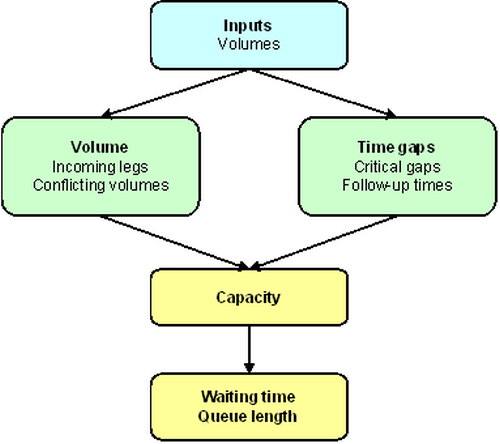
Image 77: Calculation process for roundabouts according to HCM 2010
If you use the HCM 2010 operations model for roundabout nodes, the Visum attributes listed in Table 116 will show effect. Make sure that they are set to realistic values prior to running the analysis.
|
Network objects |
Attribute |
Description / Effect |
|
Geometry |
All |
Geometry data of lanes, lane turns and crosswalks |
|
Nodes |
ICAShareCAVs |
Optional consideration of the share of autonomous vehicles. The value range is between 0 and 100%. The attribute is taken into account for the calculation of capacity from HCM 7th Edition. |
|
Nodes |
ICAPHFVolAdj |
Factor for adjustment of initial volumes to peak volumes. Then, volumes are divided by both node and turn adjustment factors. |
|
Turns |
ICAPHFVolAdj |
|
| Leg | Has Center Island |
Indicates whether the leg has a center island (yes/no) |
|
Leg |
Center island length |
Length of center island |
|
Leg |
Center island width |
Width of center island |
|
Leg |
Channelized turn length |
Length of channelized turn |
|
Leg |
Has splitter Island |
Indicates whether a leg has a splitter island (yes/no) |
|
Leg |
Length of splitter island |
Length of the splitter island Note Value entered is used if the Has splitter island attribute is activated. |
|
Leg |
Splitter island width |
Width of splitter island Note Value entered is used if the Has splitter island attribute is activated. |
|
Leg |
Has bypass lane |
Indicates whether the leg has a bypass lane (yes/no) |
|
Leg |
ICA Share of bypass volume |
Proportion of right turns (left-hand traffic: left turns), which use a bypass lane for the turn movement. Note This information is used if the Has bypass lane attribute is activated. |
|
Leg |
Number of conflict lanes |
Number of conflict lanes in roundabout for incoming leg Note HCM only distinguishes between single- and double-lane roundabouts. |
|
Lane |
ICA Preset critical gap |
Critical gap value of your choice |
|
Lane |
ICA Use preset critical gap |
Optionally, you can overwrite the critical gap used in Step 5. The analogous value of the turn is not used. Activate this option to use the critical gap set. |
|
Lane |
ICA Preset follow-up time |
Follow-up time value of your choice |
|
Lane |
ICA Use preset follow-up time |
Optionally, you can overwrite the follow-up time used in step Step 6. The analogous value of the turn is not used. Activate this option to use the follow-up time set. |
Table 116: Input attributes for roundabout nodes according to HCM 2010
Output is available through the same attributes as for signalized nodes (Table 101).
The calculation method according to HCM 2010 consists of twelve consecutive steps. Here, the description is reduced to the most important steps.
Step 1: Calculate flow rates (volumes) for each turn
The turn volumes are converted by multiplying them with the peak hour factors of the turns and the node in values for the 15 minute peak.
Step 2: Calculating traffic flows for each lane and conflicting volumes for each approach
All calculations are based on the traffic flows and conflicting volumes at each approach. These flows are derived from the turn volumes (in Image 78) for a roundabout with four approaches (v1 to v12).

Image 78: Approaching flows at a four-leg roundabout
For the distribution of the volumes to the lanes please refer to HCM 2010, pages 21-14 and 21-15.
Example
The flow from the south is the sum of turn volumes v7 + v8 + v9. The conflicting flow which applies to this flow is however the sum v1 + v2 + v10. This approach can be applied to roundabouts with a countless number of approaches. U-turns can also be considered in the same way if you want to integrate them in the ICA calculation.
If an approach has more than one lane, the total inflow is distributed on lanes.
1. If only one lane is permitted for left turns, its volume is the sum of all volumes of left turns.
2. If only one lane is permitted for right turns, its volume is the sum of all volumes of right turns.
3. The remaining volume is distributed to all lanes in such way, that they all have the same volume if possible.
Step 4: Capacity
The capacity of each lane is assigned to all turns, for which lane turns are defined starting from the lane. The result is saved in PCU/h in the turn attribute ICA final capacity.
For each of the cases, predefined formulas can be used (HCM 2010, equations 21-1 to 21-7). This is the basic formula:

Here B equals 0.001 for one-lane and two-lane entry roads to single-lane roundabouts. For single-lane approaches to two-lane roundabouts B equals 0.0007. Two-lane approaches to two-lane roundabouts use the following values for B: 0.00075 for the inner-most (let) lane, and 0.0007 for the right lane. For bypass lanes, with one conflicting exit lane, B is assumed to be 0.001. 0.0007 is used if there are two conflicting exit lanes.
In the HCM 6th Edition, the factors were adjusted as used in the following formulae:
 for single lane approach to a single lane roundabout
 for two-lane approach to a single-lane roundabout
 for single-lane approach to a two-lane roundabout
 right lane of a two-lane approach in a two-lane roundabout
 left lane of a two-lane approach in a two-lane roundabout
 for a bypass lane with a conflicting exit lane
 for a bypass lane with two conflicting exit lanes
The formulae correspond to the equations 22-1 to 22-7 in the HCM 6th Edition.
In the HCM 7th Edition, the share of autonomous vehicles is also considered (see Equations 33-1 and 33-2, respectively, and Exhibits 33-12 and 33-13).
The calculation of the capacity takes into account whether the default critical gaps and/or follow-up times were changed by the respective Visum attributes. For the control type 'roundabout', critical gap and follow-up time are set by lane. Turn-related values of this attribute are not regarded. For the extended computation, the capacity is derived from the following data (HCM 2010, page 33-3):

Depending on the changed values for the critical gaps and/or follow-up times, different values are taken into account for A and B. If the attribute ICA Use preset follow-up time is active, the calculation of A is determined according to chapter 33 of the HCM 2010. This calculation corresponds to equation 21-22:

Otherwise, value A is determined according to the first part of chapter 21 of the HCM2010. This means that the default values for the follow-up time of chapter 33 are never used for A.
If the attribute ICA Use preset critical gap has been set, the values of the follow-up times from chapter 33 are used for B, unless the follow-up time is overwritten as well. In the latter case, the overwritten value will be used.

where
|
c |
capacity in PCU/h |
|
v |
conflicting flow in PCU/h |
|
gapc |
critical gap in s |
|
gapf |
follow-up time in s |
Visum uses the following default values: 4 s for the critical gap and 3 s for the follow-up time. You can optionally overwrite both values by lane.
Pedestrians have a bearing on the capacity. For a detailed description, please refer to HCM 2010, pages 21-16 and 21-17.
The capacity of each lane is assigned to all turns, for which lane turns are defined starting from the lane. The result is saved in PCU/h in the turn attribute ICA final capacity.
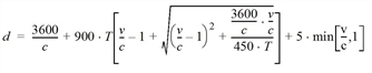
The mean wait time on a lane of an approach arises from the following values:
|
d |
mean delay in s/PCU |
|
c |
lane capacity in PCU/h |
|
v |
lane volume in PCU/h |
|
T |
observation period in h |
The mean delay of a turn is the volume weighted mean of the mean delay of lanes used. The result is saved in the turn attribute tCur.
The mean queue length on a lane of an approach arises from the following values:
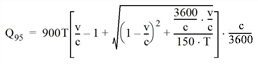
where
|
Q95 |
95% percentile of queue length in PCU |
|
c |
lane capacity in PCU/h |
|
v |
lane volume in PCU/h |
|
T |
observation period in h |
The attribute ICA back of queue for defined percentile is the maximum of the Q95 percentiles for the lanes used.
Step 7: Level of Service (ICA LOS)
LOS per lane of an approach is defined as a classification of the mean delay (Table 117).
|
LOS |
Mean Delay [s / PCU] |
|
A |
0 - 10 |
|
B |
>10 - 15 |
|
C |
>15 - 25 |
|
D |
>25 - 35 |
|
E |
>35 - 50 |
|
F |
>50 |
The HCM does not determine the calculation of the LOS per approach, turn or node. In these cases Visum calculates the LOS on the basis of the volume weighted mean delay. If the volume exceeds the capacity, the LOS is automatically set to F.
