Prerequisite is that no boundary has been defined yet for the desired network object.
1. Under Edit > User preferences > User interface > Network editor, select option Permit interactive editing of geometries.
|
Note: Alternatively, on the toolbar of the Network editor, click the |

2. Mark the desired network object (Marking network objects in the network).
3. Right-click the marked object.
4. On the shortcut menu, click Create face.
Visum switches to the Insert mode for boundaries.
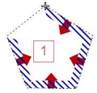
5. Insert at least three polygon points where you need them with consecutive anti-clockwise clicks.
|
Note: You can also use polygon points of existing polygons for the new polygon. To do so, under Edit > User preferences > User interface > Network editor, select option Automatic snapping of vertices and specify a Snap radius (Merging polygon points of two polygons). |
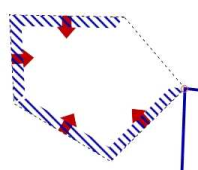
The edges of the boundary polygon are displayed as a rubber band. The hatching and the arrows indicate the direction of the surface (Fundamentals: The surface data model in Visum).
|
Notes: Even though you can also insert the polygon points in a clockwise direction, this would create a so-called negative face (=hole), which cannot be saved as boundary as no surface exists yet from which it can be cut out (Fundamentals: The surface data model in Visum). If you have selected the Automatic snapping of vertices option on the Edit menu under User preferences > User interface > Network editor, adjacent points of other polygons or allowed point objects are displayed as small squares. The square at the mouse pointer snaps to a square as soon as you get close enough. This way, you can use existing points explicitly. If you shift the polygon point later on, both polygons will be changed automatically. |
6. Confirm the definition of the boundary by placing the last point of the polygon on top of the first point or press Enter.
The boundary is created and the polygon points are highlighted.
|
Note: If you confirm the definition of the boundary with Enter, the coordinates of the click point are not saved as polygon point. |
|
Tip: You can use parts of existing faces when creating a new boundary if you hold down the Ctrl key while clicking the first point of the polygon to be used and then clicking the last point. In a preview, you can see which points will be used and in which direction the polygon runs. |
7. If required, reshape the boundary (Managing boundaries of polygonal network objects).
This option merges polygon points that you inserted with the snap function with the original polygon point. If you shift the polygon point later on, both polygons will be changed automatically.
8. Confirm with OK.
Depending on the network object type, the following applies:
- In case of zones, territories, and polygonal POIs, the new boundary is created and the step ends here.
- In case of main nodes, main zones and
9. Confirm with Yes.
The network objects (nodes, zones or links) which are within the boundary, are allocated to the higher-level network object (main node, main zone, or
|
Note: If you want to create the main node, the main zone, or |
