If you are in the network in the Edit mode and double-click one of the network objects nodes, main nodes, turns, or main turns, the junction editor opens. Here you can further model the network object (Fundamentals: Junction modeling).
You can edit the following network objects in the junction editor:
- Editing a node in the junction editor
- Editing a main node in the junction editor
- Editing turns in the Junction editor
- Editing main turns in the Junction editor
- Editing links in the Junction editor
- Managing signal controllers
- Managing signal groups
- Editing the geometry of a node
- Editing the signal times of a node
- Managing signal coordination groups
- Calculating and exporting ICA
- Optimizing signal cycles and split of a single signal controller
- Using turn volumes in the Junction editor
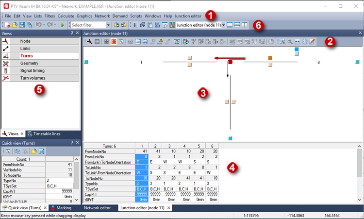
(1) Menu bar
As soon as the junction editor window is open, the menu bar displays the Junction editor menu. Among others, it contains all functionalities of the junction editor toolbar.
(2) Junction editor tool bar
The following functions, among others, are available in the toolbar. Depending on the selected view, not all symbols are available.
|
Symbol |
Name |
Description |
|
|
Select node |
Selection of a node in the Find node window. |
|
|
Select main node |
Selection of a main node in the Find main node window. |
|
|
No synchronization with other windows |
The junction editor is not synchronized with other windows. |
|
|
Synchronization with other windows: Highlight |
The junction editor is synchronized with other windows. |
|
|
Select attributes |
Selection of the attributes which are displayed in the list view of the junction editor. |
|
|
Open list layout |
Opens a layout file for the list view of the junction editor. |
|
|
Save list layout as |
Saves the layout of the list opened in the junction editor. |
|
|
Execute ICA calculation |
Starts the ICA calculation (Starting an ICA calculation). |
|
|
Open/close ICA report window |
Opens/closes an Excel sheet with a report (Displaying the ICA calculation in the report window). |
|
|
Enable/disable automatic ICA calculation after network changes |
If this function is activated, Visum recalculates the ICA automatically each time an object or attribute is changed (Recalculating ICA automatically). |
|
|
Export ICA report to Excel |
You can save the current ICA calculation to an Excel file by clicking the symbol (Exporting an ICA report). |
|
|
ICA calculation status |
Checks whether an ICA calculation can be run (Checking the status of ICA calculations). |
|
|
ICA signal cycle and split optimization |
Via the icon, you can optimize the signal cycle and split (Optimizing signal cycles and split of a single signal controller). |
|
|
Vissim node preview |
Opens the Vissim export preview. It shows the selected node and the adjacent nodes. |
|
|
Create signal controller |
Use the symbol to create a signal controller. Note The signal controller will automatically be allocated to the currently displayed node/main node if the Signalized control type has been selected. |
|
|
Edit signal controller |
Use the symbol to edit a signal controller. |

|
Switch on/off signal controller |
You can activate and deactivate a signal controller using this symbol. |
|
|
Edit VISSIG controller/Edit RBC controller |
|
|
|
Remove signal controller |
Use the symbol to delete a signal controller. |
|
|
Create signal group |
Use the icon to create a signal group. |
|
|
Remove signal group |
Use the symbol to delete a signal group. |
|
|
Convert to external control/Convert signal controller to Visum controller |
Use the symbol to convert an existing signal controller into an external controller and edit it with the Vissig program, or convert an external controller into a Visum controller. Note This function is only provided with the Vissig add-on activated. |
|
|
Update control data of the signal controller |
Click the symbol to read current data from the control file. Note The symbol is only provided for signal controllers of the type Vissig. |
|
|
Use stage templates |
You can use the symbol to apply existing stage templates to generate stages in the Signal timing view (Generating stages from templates). |
|
|
Create stage |
Use the symbol to create a stage. |
|
|
Remove stage |
Use the symbol to delete a stage. |
|
|
Edit time-varying attributes |
Use the symbol to edit time-varying attributes of the currently displayed network object if time-varying attributes have been created beforehand (Edit time-varying attributes). |


(3) Schematic view of the selected object
The schematic view displays the currently selected object.
You can change the section displayed in the junction editor window. Similar functionalities as those in the Network editor window are provided for this(Network editor window).
(4) List view of the selected object
The list view shows the attributes of the selected object. You can edit the attribute values of editable attributes right in the list.
|
Notes: You can select a font for the list view and specify, whether the Short name or the Long name of the attributes shall be displayed in the list view (Adjusting the display and the input options of the list view). The Signal timing view does not show attributes below the node but the signal times of the node, which you can edit (Editing the signal times of a node). |
(5) The Views window
Here you can select an object type. If you switch to another object type in the Views window, the schematic view and the list view will display the new object. The following views are provided:
- Nodes
- Main nodes
- Links
- Turns
- Main turns
- Geometry
- Signal timing
- Turn volumes
|
Note: The Nodes, Main nodes, Links, Turns, Main nodes, and Turn volumes views are available to all users. The Geometry and Signal timing view are available with the Junction editor and control add-on (Displaying details on program and license). |
(6) Window selection
Via the drop-down list, you can switch between all open windows.
