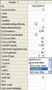
In the list view, each row describes a node property.
1. In the network, double-click the node that you want to edit.
The Junction editor displays the selected node, the list view displays corresponding properties.

2. Make the desired changes here.
|
Note: Some layout and editing functions can be found in the shortcut menu of the list and the header row. |
Editing node attributes
You can edit the editable attributes of the node in the list in different ways, depending on the attribute:
- Double-click the desired row and enter the new value.
- Perform an arithmetic operation for one or multiple values (Editing attribute values in the Quick view with arithmetic operations)
- Select the desired value via a drop-down list
- Select/deselect an option per mouse click
- Use buttons to select values in a separate window
|
Note: The input options of the list view depend on the setting under Edit > User preferences > entry User interface > Junction editor (Adjusting the display and the input options of the list view). |
You can, for example, display the following node attributes in the list view.
|
Note: You can edit the attribute selection of the list (Adjusting the attribute selection in the Junction editor). |
|
Element |
Description |
|
Number |
Unique number of the node The nodes are numbered consecutively. You can overwrite the preset number with a number that does not yet exist in the network. Note If you edit the node number, existing assignment results will be deleted for all demand segments. |
|
Type number |
The node type (0...99) categorizes the node for the definition of turn standards (Managing turns). Note The standard type is 0. |
|
Code |
Code of the node |
|
Name |
Name of the node |
|
AddValue1 - AddValue3 |
Free attributes which you can use to enter additional values. Tip If you want to allocate additional information to a network object, you can also create user-defined attributes (Managing user-defined attributes). |
|
Capacity PrT |
Allowed hourly PrT capacity of the node |
|
t0 PrT |
Private transport turning time in an unloaded network |
|
X-Coordinate Y-Coordinate Z-Coordinate |
Coordinates of the node in the network The coordinates are assigned automatically according to the set coordinate system (Selecting a coordinate system). Tip You need Z-coordinates (height) for the 3D display in Vissim The elevation data is exported during an ANM export. |
|
Control type |
Use the drop-down list to select the control type of the node.
|
|
Use preset method for impedance at node |
|
|
Method for impedance at node |
You can use the list box to select a method for the impedance calculation of the displayed node if the Use preset method for impedance at node option has been selected (Selecting the method for node impedance calculation). |
|
ICA sneakers |
Minimum number of vehicles in [veh/cycle], which make a successful left turn (right-hand traffic) or a successful right turn (left-hand traffic) Note One value applies to all movements at the node. |
|
ICA peak hour factor volume adjustment |
Factor for adjustment of the initial volume to the peak period Enter a value between 0.25 and 1. Note Volumes are multiplied by both node and turn adjustment factors. |
|
ICA is central business district |
Specify whether the main node lies within the CBD |
|
ICA use preset loss time |
|
|
ICA loss time |
For nodes with a signal group-based controller, to which no signal controller has been allocated, you can specify a user-defined loss time. |
|
Design volume |
Sum of the volumes of all turns in vehicles and car units |
|
Design volume capacity ratio PrT |
The definition of this value depends on the impedance calculation at the node. By default it equals the quotient of the total volume and the total capacity of the node, i.e. in each case the total of the respective values of all turns. |
|
Turn tCur mean |
Mean waiting time per car unit |
|
Turn tCur total |
Total of the wait times of all turns within the design time interval |
|
Turn tCur maximum |
Maximum waiting time for a car unit |
|
Has automatic major flow |
Calculated attribute which indicates whether a manual or an automatic major flow exists |
|
Signal controller |
Here you can edit the allocation of the node to a signal controller. Tips The control type of the node must be signalized. You have to create a signal controller, before you allocate a node to it (Creating a signal controller). |
|
Main nodes |
Here you can edit the allocation of the node to a main node. |
The following attribute is only displayed if a geometry template has been defined:
|
Element |
Description |
|
Apply geometry template |
Here you can select a geometry template which shall be used for the node. Tip Geometry templates can be created in the Geometry view (Creating a geometry template). |
 If the option has been selected, the method set under attribute
  If the option has not been selected, the
