Add-on module external signal control signal controller
|
|
Note: You must have a license for the add-on module. |
With the add-on module, you can simulate signal control procedures. These are available as a separate executable program (*.exe) or program library (*.dll). These can be either standard procedures supplied by PTV GROUP or other providers, or procedures developed internally with the API module.
The files must be in the programming language C or C++.
|
|
Note: The DLL files must be compiled appropriately for the Vissim-64-bit version in use. |
Some control procedures expect the supply file to be saved in the same directory that contains the *.inpx file. If a control file is saved to a directory that does not meet the requirements of the control procedure, this can cause the program to crash. The supply files of the control procedures Fixed time/Vissig, VAP and RBC can be saved to any directory Vissim can access. Vissim does not need the supply files to be saved to a specific directory. Should you have any questions regarding supply files, please contact the company that developed the control procedure.
If you have a license which includes the signal controller type External, the API source code modules and the documentation can be found in the API directory of your Vissim installation.
1. On the Signal Control menu, click > Signal Controllers.
The Signal Controllers list opens.
2. Right-click the entry of your choice.
3. On the shortcut menu, click Edit.
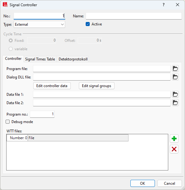
The Signal Controller window opens.

4. In the Type field, select > External.
5. Make the desired changes:
| Element | Description | ||
|---|---|---|---|
|
Program file |
ProgFile: User-defined DLL file with control logic |
||
|
Dialog DLL file |
GUIFile: User-defined DLL file of supply interface |
||
|
Data file 1 |
SupplyFile1: Data for the control logic
|
||
|
Data file 2 |
SupplyFile2: Data for the control logic |
||
|
Program number |
ProgNo: The signal program which is to be simulated. The signal program number can be specified for a signal controller of type External. This is also possible during the simulation run. |
||
|
Debug mode |
Debug mode enabled (Debug): |
||
|
WTT files |
WTTFile: Value type tables: The tables contain the data types of the control logic and the type of display in the signal controller detector record (Evaluating signal controller detector records) or in the Signal times table window (Showing signal times table in a window). By default, a vissig.wtt file is saved to the Exe directory of your Vissim installation. The WTT file must not necessarily be specified. |
File names with a path for the program file, the dialog DLL and the *.wtt files can be transferred to external signal controllers. The paths are stored as relative paths. They contain the current data directory in which the *.inpx network file is stored as well as the program directory with the VISSIM240.exe file. Thus these can still work even after the data directory is moved or copied to another computer.
|
|
Note: The signal program number for a signal controller of type External can also be specified during the simulation run. The signal program is then changed during the next switching time. |
Documentation in English
- ..\<Vissim Version>\API\SignalControl_DLLs\SC_DLL\SC_DLL_Interface.doc
Examples
- ..\<Vissim Version>\API\SignalControl_DLLs\Examples\

 If this option is selected, the signal flow can be followed during simulation.
