Placing the routing decision and the mode of action in the simulation
Mode of action of routing decisions for routes
If no route is assigned to a vehicle in a simulation run, the vehicle is assigned its route as soon as a routing decision marker traverses it.
One of several routes at a routing decision point is selected based on the route choice method, which is either the Monte Carlo method, i.e. proportional to the relative volumes on each vehicle route, or a user-defined formula. Using the formula, you calculate the share of vehicles for the vehicle route depending on the attributes and attribute values of the vehicles.
On links with multiple lanes, a vehicle driving on a route attempts to independently choose a lane for the relevant connector according to the Lane change attribute value set (Lane change distance, if Fixed value is set: default 200 m), so that the connector can be reached without further lane changes. Long advance links allow the vehicles a timely classification (pre-sort). In unfavorable cases, for example, when the advance link which is selected is too short, it is possible that many unrealistic lane changes lead to traffic disruptions, which do not exist in reality. Most of the time such cases are preventable using suitable modeling.
In 2D animation, a current change of lanes, as well as the desire to change lanes is visualized via a small red line to the right or left of the vehicle (representing the turn signal), from the defined Lane change distance on. This is also the case for lane changes on connectors.
In 3D animation, a current lane change and the desire to change lanes is shown via a turn signal, if this is defined for the 3D model of the vehicle.
Vehicles in the adjacent lanes decelerate partially cooperatively in order to allow the blinking vehicle to merge (Applications and driving behavior parameters of lane changing).
Mode of action of routing decisions for partial routes
Partial routes can be used, for example, for variable message signs to model multiple alternative routes, without having to change every single route that leads to the position of the variable message sign. If two alternative routes are possible, only one of the partial routing decisions with two routes must be defined, which is assigned to the total volume for each desired share.
Positioning of routing decisions
- If you define routes for links with multiple lanes, you must position the routing decision adequately far enough from the point in which the routes separate. This will prevent unrealistic jams, which occurs because the decision marker assigns all vehicles a route and not just a portion of the vehicles. This allows more lane changes to take place in the simulation than are possible in reality.
- Position the routing decision section so that it is located before the end of the longest known jam in this section.
- When you insert numerous routing decisions, for example, in order to model turns per intersection separately, a vehicle with an active routing decision transverses and ignores these routing decisions until it has reached the destination section of its route. In order for a vehicle to switch from route to route successfully and thus follow each route consecutively, the end of the first route must be in the movement direction; only afterwards can the second route begin. To do this, position all destination sections (turquoise) of a route on the first connector or at the corresponding position of a link behind the last decision marker of this route. Once you have positioned all start sections (purple) on a link behind the intersection and at the end of all connectors, ensure that all preceding routes end before the start of a new route.
- Managed lanes routing decisions and dynamic routing decisions must not be defined within meso network nodes or meso nodes.
|
|
Note: Routing decisions are, like all other decision markers, relevant for a vehicle only after the subsequent time step. Therefore the distance between the decision marker and the subsequent link or connector must be defined at least large enough so that the length of the path corresponds to the vehicle with the highest possible desired speed within a time step. If this is not ensured, it is possible that some of the vehicles will not be influenced by the routing decision. |

|
|
Note: If a vehicle on a route at the last possible position (emergency stop distance) is waiting for an opportunity to change lanes, but this cannot occur within 60 seconds, this vehicle is removed from the network. Otherwise unrealistic interferences and queues will arise. In reality, one can assume that vehicles waiting to change lanes will be compelled to "squeeze in" after a short period of time. You can adjust the standard value of 60 s in the driving behavior parameter Diffusion time of the lane change (Editing the driving behavior parameter Lane change behavior). |
|
|
Notes:
|
Mode of action of routing decisions of the type Managed Lanes
Routing decisions of the type Managed lanes (managed lanes routing decisions) influence the path selection behavior of vehicles in the simulation that are already on a static route or on one of the two routes (managed lanes or all-purpose route) that begin at a routing decision of the type Managed lanes facilities. If a managed lane route traverses a connector blocked for all vehicle classes, the corresponding managed lanes routing decision does not apply.
This also influences vehicles on the paths of a dynamic assignment. If a managed lane route traverses a blocked edge of dynamic assignment, the corresponding managed lanes routing decision does not apply.
If several managed lane routing decisions are located at the same position, the vehicle shall be affected by the managed lane with the lowest managed lane routing decision number.
Positioning routing decisions of the type managed lanes
You can define routing decisions of the type Managed lanes by section or add multiple routing decisions before the managed lane starts. This choice depends on whether the driver shall decide on how many sections to traverse before reaching the first section or whether he shall make that decision each time before reaching one of the sections.
Positioning routing decisions of the type Managed lanes by section
This option is useful, if in reality the toll is displayed at the routing decision for the next section and the driver is only then to decide whether to use the toll route:
- Place a routing decision on the toll-free part of the highway, before each access from the toll-free part of the highway to the parallel-running toll part of the highway.
- For each of these routing decisions, place the destination behind the next possible exit from the toll part to the toll-free part of the highway.
- Place a routing decision on the toll road of the highway, before each access from the toll part to the toll-free part of the highway.
- On each of the toll-free parts of the highway, for each of these routing decisions, place the destination behind the next possible exit from the toll road to the toll-free part of the highway.
Inserting routing decisions of the type Managed lanes at the beginning of managed lane
This option is useful, if in reality the toll is displayed for individual sections of the total toll distance before the first routing decision, nothing changes at the end of the first section and no other toll is displayed there.
Using multiple, successive routing decisions, you can model various toll route options for a driver. If you e.g. want the vehicle to be able to use one, two or three managed lane segments, position the most expensive routing decision option on the toll-free route, so that the vehicle has to traverse it first, then drives downstream to the next expensive routing decision option and last to the least expensive routing decision option. Place these types of routing decisions on toll-free routes only.
For routing decisions of the type Managed Lanes that follow upon each other at a distance of less than10 m, the following applies: If the vehicle has selected a managed lane based on one of these routing decisions, you cannot use another routing decision of this group that lies further downstream to assign the vehicle a different toll lane. As soon as the vehicle has selected a managed lane, it ignores any other managed lane routing decisions of this group that lie further downstream.
Probability of switching to a toll lane
At the first passing of a routing decision of the type Managed Lanes each vehicle receives a random number for the probability that it will change to the toll lane. This random number is then used for all further routing decisions of the Type Managed Lanes . This ensures that the vehicle will only change its original decision when a completely different traffic-related state ensues.
Assigning routing decisions of the type Managed lanes facilities to individual managed lanes facilities
By default, to model managed lane routes of different lengths you use different routing decisions of the type Managed lanes facilities. You then assign an individual managed lanes facility to each of these routing decisions. This way, you ensure that an individual decision model and toll calculation model are valid for each managed lanes route and that the different travel times are not averaged.
Two routing decisions of the type Managed lanes facilities should only use the same managed lanes facility in the event that the all-purpose routes of both routing decisions and the managed lane routes of both routing decisions are mostly identical. This may be the case, for example, if you model a high occupancy toll lane for certain vehicles on a highway parallel to toll-free lanes.
Modeling the toll part of a highway
The toll part of a highway can be a structurally separate road parallel to the toll-free lanes of the highway. You use links and connectors to define both parts of the highway and the ramps for entries and exits. You use routing decisions of the type Managed lanes, the respective toll route and toll-free route to model the use of these parallel lanes per section. To enable the vehicle to decide whether to use the high occupancy toll lane or the toll-free part of the highway, place the Managed lanes routing decision before the branching between the toll route and the toll-free route. Then have one of these two routes run along a different link sequence that starts at the same managed lanes routing decision and ends at a common destination cross section (Modeling a separate route course for the toll route and toll-free route).
The toll part can also be a high occupancy toll lane (HOT lane):
- On a high occupancy toll lane, vehicles whose number of passengers falls below a specified value are subject to toll.
- Vehicles on the HOT lane are toll-free if the number of passengers exceeds a specified value, for example buses, taxis and HOV3+ vehicles (vehicles with more than three passengers, for example).
Use occupancy distribution to assign the number of occupants for the vehicles of a vehicle type (Using occupancy distributions). The occupancy rate of the vehicle is taken into account in the toll pricing calculation model (Defining managed lane facilities), (Defining toll pricing calculation models). Using the toll pricing calculation model, you can take current traffic conditions into account by defining the influence of travel time savings and average speed on toll costs. The decision model defines the probability of using the toll route depending on the vehicle class to which a vehicle is assigned (Defining decision model for managed lane facilities). You group the vehicle types that can use the HOT lane toll-free into one vehicle class. These vehicles always use the toll-free route.
For path selection in the Vissim network, dynamic assignment takes link sequences without toll routes into account as well as link sequences on which managed lane facilities and toll routes have been defined (Defining a vehicle route of the type managed lane).
Determining the number of managed lane routes based on possible paths - examples
In the Vissim network depicted in the following figure, the highway branches downstream of node 1 into a managed lanes part (upper link sequence, red) and a toll-free part (green). In the further parallel course of the link, a ramp enables the vehicles to change from the toll-bearing part to the toll-free part. The link sequences of the managed lanes and toll-free parts are reunited upstream of node 2. The lower link sequence via nodes 4 and 3 allows vehicles to bypass the highway.
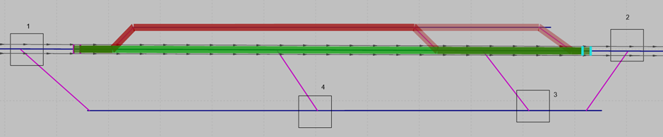
For comparable use cases in which the vehicle can optionally continue on or leave the managed lanes part to switch to the toll-free part, you define a managed lanes routing decision with a managed lanes route and a toll route for each possible path and adjust the route course:
1. Define a managed lanes routing decision upstream of the branching of the toll and toll-free parts of the highway (Defining a vehicle route of the type managed lane).
2. Add the common destination section of the respective toll route and toll-free route downstream of the junction of the toll and toll-free parts of the highway.
3. Move the destination section and separate the course of the toll route from that of the toll-free route (Modeling a separate route course for the toll route and toll-free route).
4. Repeat these steps for a managed lanes routing decision, whose toll route leads via the toll part of the highway and then over the ramp and the toll-free part of the highway to the destination section. Again, separate the toll route from the toll-free route.
If you model several ramps, the vehicle can decide in sections whether to use a ramp to switch from the toll lane to the toll-free lane. After traversing a managed lanes routing decision, the vehicle ignores all other managed lanes routing decisions for the following 10 m.
Toll routes In dynamic assignment
Dynamic assignment does not decide at the start of the journey whether the vehicle uses the toll route or the toll-free route. If the use case in the above figure is simulated using dynamic assignment, the latter decides when the vehicle starts driving whether it will take the lower path via nodes 4 and 3 or the upper path via the toll routes. Only after the vehicle has driven straight through node 1 and has reached the managed lanes routing decision downstream of node 1 does it decide whether to take the toll-free route straight ahead or the upper route that is subject to toll (Calculating toll using dynamic assignment).
Requirements of dynamic assignment for modeling separate toll routes
In addition to changing from the toll part of the highway via a ramp to the toll-free part, you can also use a ramp to model the change from the toll-free lane to the toll- lane in sections:
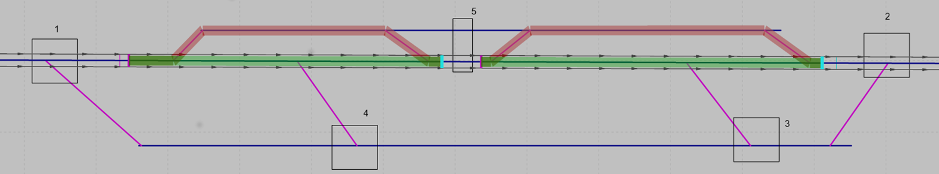
- Insert a node upstream of each ramp that connects the toll-free link sequence with the toll-bearing link sequence. The node must extend over both link sequences (node 5).
- The destination section of the toll route and the toll-free route of the section must be placed in front of the node.
- In addition to the toll route and the toll-free route for each section, you can define a toll route and toll-free route that runs along the entire link sequence. To do so, place the managed lanes routing decision downstream of node 1 and upstream of the branching of the toll-free route and the toll route, whose destination section you need to place downstream of the final merging of the toll-free route and the toll route, upstream of node 2. Move the destination section and separate the course of the toll route from that of the toll-free route (Modeling a separate route course for the toll route and toll-free route).
