Generating a railway crossing
In the network editor, you can generate a railway crossing on one or more links, including all the necessary objects and a simple, traffic-actuated control. To do so, on the link with the railway tracks, define the start and end of the railway crossing for the secondary direction of the 2-stage controller it is based on. Vissim records the links that cross this section as the main direction. Roads or railway tracks can be defined as links for the main direction.
Before you confirm creation of the railway crossing, you can adjust the values of relevant attributes, such as clearance times and the distance of the call detector from the stop line of the train. When inserting the call detector, Vissim checks the position resulting from this distance. If the position is not possible due to conflict areas or connectors, Vissim moves the call detector to the next possible position upstream or downstream.
Once you confirm the definition, Vissim inserts the following objects:
-
A signal controller of the type Railway Crossing in the main direction upstream of the first crossing link of the railway tracks. Vissim then assigns two signal groups of the type Normal to this signal controller.
-
A signal controller on each crossing link of the secondary direction, with a common signal control. You do not have to program this signal control, as Vissim generates it and assigns a signal sequence to the signal groups (Modeling signal controllers). Standard length signal head to the conflict area 1 m.
-
A call detector and a checkout detector for the signal heads on each crossing link of the secondary direction. Standard length detector 2 m. Position checkout detector: 1 m downstream of the last conflict area.
- Conflict areas with Passive status in the node of the main direction and secondary direction.
During the definition of the objects in the network editor, the Short help is displayed, in which the necessary steps are described. You can show and hide the short help (Becoming familiar with the user interface).
Generating a railways crossing in the network editor
1. Make sure that the links you want to define for the main direction and the secondary direction are assigned the required link behavior types and display types. For the secondary direction, this can be, for example, the display type Rail (road) or Rail (stones).
2. On the network editor toolbar, on the very left, click the Create railway crossing button  .
.
The Create railway crossing window opens and displays the attributes.
3. Make the desired changes:
| Long name | Short name | Description |
|---|---|---|
| Minimum green time railway | MinGreenRail |
Minimum time during green interval for the railway. Default 5.0 s |
| Clearance Time Rail | ClearTmRail |
Time [seconds] that may elapse between the free driving time of the checkout detector and the start of the green interval for street traffic. Default 0.0 s |
| Minimum green time Street | MinGreenRoad |
Minimum time during green interval for street traffic. Default 5.0 s |
| Clearance time road | ClearTmRoad |
All-red duration [s] after the road signal turned red until the rail signal turns green. Default 5.0 s |
| Call detector - position before stop | CallDetPosBefStop |
Distance between the calling detector and the stop line of the train Default 200 m |
If you move the mouse pointer to a link, a circular selection area is displayed around the mouse pointer.
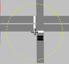
Depending on the position of the mouse pointer, white markers show the positions of the beginning of the railway crossing and the signal heads.
4. Go to the link of the secondary direction and click the desired position of the starting point of the railway crossing.
5. Then go to the link of the secondary direction and move the cursor to the desired position of the end point of the railway crossing.
A preview in the Network editor shows white markers at the positions of the beginning and end of the railway crossing and signal heads. Red markers show the positions of the signal heads. Markers that are not relevant are first displayed in a darker color. Once you have completed the next step, they are no longer displayed at all. The call detector is inserted in the secondary direction.
6. Then go to the link of the secondary direction and click the desired position of the end point of the railway crossing.
7. In the Create railway crossing window, click  to confirm.
|
|
Tip: Alternatively, you can define the railway crossing manually by following the steps below and then editing the attributes. |

Defining an alternate railway crossing in the list
1. On the Signal Control menu, click > Signal Controllers.
The Signal Controllers list opens.
The attribute and attribute values of this network object type are shown in the list on the left, which consists of two coupled lists.
2. In the list, on the toolbar, click the Add button  .
.
A new row with default data is inserted.
The Signal Controller window opens.
3. In the Type field, select Railway Crossing .
4. In the upper section, enter the desired basic attributes (Attributes of signal controllers).
5. Confirm with OK.
6. Save the network file *.inpx.
You can edit the attributes in the attributes list (Attributes of signal controllers).
7. Insert a new signal head at the desired position at the railway crossing (Defining signal heads).
8. In the attributes of this signal head or the SC Signal Group, select the signal controller of the type Railway Crossing you defined.
9. Insert a new detector at the desired position of the railway crossing (Defining detectors).
10. In the attributes of this detector for the SC, select the signal controller of the type Railway Crossing you defined.
