
Note: In lists, you can use the  Attribute selection icon to show and hide attribute values (Selecting attributes and subattributes for columns of a list).
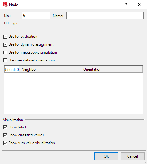
The Nodes window opens when you insert a network object and have selected to have the Edit dialog automatically opened after object creation (Right-click behavior and action after creating an object). By default, only the Nodes list is opened.
Into the window, you enter attribute values for the network object. For network objects which have already been defined, you can call the window using the following functions:
The network object may have additional attributes. In the network objects list of the network object type, you can show all attributes and attribute values. You can open the list via the following functions:
In the network objects list of the network object type, you can edit attributes and attribute values of a network object (Selecting cells in lists), (Using lists).
The objects of this object type may have relations to other objects. This is why the attributes list is shown as part of a coupled list (on the left). On the Lists toolbar, in the Relations box, you can show and edit the coupled list with the attributes of the desired relation on the right (see below Showing and editing dependent objects as relation) and (Using coupled lists).
|
|
Note: In lists, you can use the |
1. Make the desired changes:
| Element | Description | ||
|---|---|---|---|
|
No. |
Unique node number |
||
|
Name |
Designation of the node |
||
|
LOSType |
Level-of-service scheme type: Basis for determining the appropriate LOS scheme for result attributes LOS(All) and LOSVal(All) in node evaluation (Evaluating nodes). The LOSTyp is defined Vissim based on the node type when the simulation run is first started:
The LOSType is only calculated in the following cases:
When you edit a node or insert a new node, Vissim defines the LOSTyp for all nodes based on the node type the next time you start a simulation. |
||
| Showing label |
|
||
|
Dynamic assignment |
Use for dynamic assignment (UseForDynAssign):
If the nodes are not used for the dynamic assignment, deactivate the option. This saves you calculation time. |
||
|
Use for mesoscopic simulation |
UseForMeso:
|
||
|
User defined orientations |
Has user defined orientations (HasUserDefOrient):
Select a direction in particular when multiple edges lead to an adjacent node and Vissim has determined an unrealistic direction. By default, in the case of multiple edges, Vissim uses the direction which occurs the most often; in the case of only two edges, it uses the direction which, in the list of available directions, occurs first (at the top, in clockwise direction). |
||
|
|||
|
Use for evaluation |
UseForEval: |
||
|
Show classified values |
Show classified values (ShowClsfValues):  Select this option to show classified values, not to show the display type selected. To show classified values, in the graphic parameters for nodes, select a color scheme and an attribute (Assigning a color to nodes based on an attribute). Select this option to show classified values, not to show the display type selected. To show classified values, in the graphic parameters for nodes, select a color scheme and an attribute (Assigning a color to nodes based on an attribute). |
||
|
Show turn value visualization |
(ShowTurnValVisual: Only active if the Use for evaluation attribute is selected, because only then can movements exist.
|
||
2. Confirm with OK.
The network object has additional attributes that you can show in the Attributes list. In the Attributes lits, the following is displayed by default:
| Element | Description |
|---|---|
|
TurnValVisualSize |
Turn value visualization size: Radius [m] of the outer circle of the the turn value visualization |
The attribute and attribute values of this network object type are shown in the list on the left, which consists of two coupled lists.
1. In the list on the left, click the desired entry.
The list on the right contains attributes and attribute values of network objects, and/or base data allocated to the network object selected in the list on the left (Using coupled lists):
2. On the list toolbar, in the Relations list, click the desired entry.
3. Enter the desired data.
The data is allocated.
 If this option is not selected, the label for the respective node is hidden when label for all nodes is selected.