
Note: In lists, you can use the  Attribute selection icon to show and hide attribute values (Selecting attributes and subattributes for columns of a list).
The Connectors window opens when you insert a network object and have selected to have the Edit dialog automatically opened after object creation (Right-click behavior and action after creating an object). By default, only the Connectors list is opened.
Into the window, you enter attribute values for the network object. For network objects which have already been defined, you can call the window using the following functions:
The network object may have additional attributes. In the network objects list of the network object type, you can show all attributes and attribute values. You can open the list via the following functions:
In the network objects list of the network object type, you can edit attributes and attribute values of a network object (Selecting cells in lists), (Using lists).
The objects of this object type may have relations to other objects. This is why the attributes list is shown as part of a coupled list (on the left). On the Lists toolbar, in the Relations box, you can show and edit the coupled list with the attributes of the desired relation on the right (see below Showing and editing dependent objects as relation) and (Using coupled lists).
|
|
Note: In lists, you can use the |
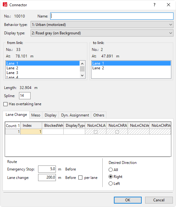
The basic attributes of the network element are shown in the upper area of the window and in the list of network objects for the particular network object type.
| Element | Description |
|---|---|
|
No. |
Unique number of the connector |
|
Name |
Name of the connector |
|
Behavior type |
Link Behavior Type (LinkBehavType): Driving behavior for the connector (Defining link behavior types for links and connectors) and (Defining driving behavior in a driving behavior parameter set). |
|
Display type |
Colored display of the connector (Defining display types) |
|
from link to link |
Lanes of the exit link (FromLink) to lanes of the next link (ToLink) between which the connector is inserted. Always select the same number of lanes in both lists. This assignment can also be subsequently edited. |
|
Length |
|
|
Spline |
Number of intermediate points for true position modeling. Intermediate points are not relevant for the driving behavior of vehicles driving on them. If you enter more intermediate points, you can model the connector more precisely. For straight connectors, start point and end point are sufficient. Up to 15 points may be useful for longer connectors, for example, for turns. When you e.g. move the start or end point of a connector to a different link or another lane, the intermediate points and the course of the connector are recalculated. You can edit intermediate points, for example by using z-Offset for each intermediate point (Defining altitude of spline points using z-offset), (Editing points in links or connectors). |
|
Has passing lane |
HasOvtLn: The inner lane may only be used for overtaking maneuvers on the oncoming lane. This is only possible on links with at least two lanes (Modeling overtaking maneuvers on the lane of oncoming traffic).
If a passing lane and regular lane of a link of the opposite direction overlap for long enough, the overlapping area may be used for passing. Only select this attribute for links on which passing is actually allowed in reality. Avoid passing lanes on which overtaking is not possible in reality, e.g. at junctions or in traffic controlled areas. You can also select this attribute for several, successive links that are connected via connectors and have at least two lanes. Vehicles can then use the entire overlapping area for overtaking maneuvers. If the passing lane is closed for a vehicle class, the vehicles of this class cannot use the passing lane for overtaking. You can place other network objects, e.g. data collection points, on passing lanes. Passing lanes are not shown in 3D mode. |
The tab contains, amongst others, the following attributes:
| Element | Description |
|---|---|
|
BlockedVehClasses |
Blocked vehicle classes: For each lane, you can select the vehicle classes for which the lane is closed (Attributes of links). If a toll route traverses a connector blocked for all vehicle classes, the corresponding managed lanes routing decision does not apply. |
|
NoLnChLAllVehTypes, NoLnChRAllVehTypes |
No lane change left – all vehicle types and No lane change right– all vehicle types: |
|
Display type |
Color of lane (Defining display types) |
|
NoLnChLVehClasses, NoLnChRVehClasses |
No lane change left - vehicle classes and No lane change right - vehicle classes: Vehicle classes, whose vehicles must not change from a chosen lane to the adjacent lane in the direction of travel. A prohibition of lane changes is shown in the 2D and 3D mode by means of a solid line. |
|
Emergency Stop |
Emergency stop distance (EmergStopDist): Is used to model the lane change rule of vehicles that follow their route, or in dynamic assignment their path, default value = minimum length = 5 m. If these lanes could not be reached before the connector at the Emergency Stop position, the vehicle stops and waits for a sufficiently large gap. The system measures upstream starting from the beginning of the connector. If a vehicle has to make more than one lane change, 5 m per lane is also taken into account in each case. If the current lane has an odd number, 2.5 m are also added to the total length of the emergency stop distance. This prevents a conflict from occurring due to identical positions of 2 vehicles which are set to change lanes on neighboring lanes. Example: A vehicle in lane 1 must change to lane 4 to follow its route or its path. An emergency stop position of 10 m was defined for the subsequent connector. The following relevant emergency stop distance is obtained for lane 1: 10 + 5 + 5 + 2.5 = 22.5 m For lane 2 accordingly: 10 + 5 = 15 m for lane 3: 10 + 2.5 = 12.5 m The actual emergency stop position is calculated as the difference between: Coordinate of the link where the connector starts minus the emergency stop distance. The result is an integer. Decimal places are not taken into account. Example: If the connector starts at 67.2 m into the link and 12.5 m have been specified for the emergency stop, this results in 67.2 - 12.5 = 54.7, emergency stop position: 54 m. The emergency stop distance of a connector A can reach upstream to another connector B. If this does not lead to a lane, from which the connector A also departs, the vehicles cannot switch lanes. In this case, Vissim automatically moves the emergency stop position upstream at least 0.1 m until the first link, where the necessary lane change is possible. |
|
Lane change |
Lane change distance (LnChgDist): Is used to model the lane change rule of vehicles that follow their route, or in dynamic assignment their path. Distance before the connector from which those vehicles, whose route or path leads across this connector, try to choose the lane in which they reach the connector without changing lanes. Standard value: 200 m, minimum value 10 m. The value must be >= emergency stop + 5 m. |
|
Per lane |
Lane change distance is per lane (LnChgDistIsPerLn )
Example: Before reaching a connector with a lane change distance of 200 m per lane, which starts from lane 1 only, a vehicle in lane 3 already starts to look for a gap to change lanes 400 m before the connector starts. |
|
Desired Direction |
Direction (Direction): Shows direction-indicator blinking signal on the vehicle during a simulation run, if the route of the vehicle leads via this connector and there is routing information available for all vehicles traversing this route:
Vehicles without a desired direction and vehicle route always drive on the next connector with the criterion All. If no such connector exists at the end of the link, these vehicles are removed from the Vissim network. The desired direction is displayed in the following order of priority: 1. Current lane change 2. Desired lane change 3. Desired direction of current link 4. Desired direction of the next route link with the desired direction right or left, if the vehicle is located within the value range defined in the attribute Lane change distance (Lane change box). 5. Turn signal direction set via external driver model in the DriverModel.DLL file (Activating external driver model via Driver Model DLL file) |
The attributes of the connector for mesoscopic simulation corresponds to the attributes of links (Attributes of links).
| Element | Description | ||
|---|---|---|---|
|
Thickness (3D) |
Thickness for the display of the connector in 3D mode. |
||
|
Visualization |
|
||
|
Show classified values |
ShowClsfValues: |
||
|
Label |
|
Only for the add-on module Dynamic Assignment (Using the dynamic assignment add-on module).
| Element | Description |
|---|---|
|
Connector closed to |
Blocked vehicle classes for dynamic assignment (BlockedVehClassesDynAssign): Via this list, you can model a multi-modal network for dynamic assignment by closing the connector for one or more vehicle classes. Thus the connector for the route selection of blocked vehicle classes is not available. |
|
Cost |
distance-dependent costs per km (CostPerKm) |
|
Surcharge 1, Surcharge 2 |
one-time surcharges that are taken into account for path evaluation. With this data, in the dynamic assignment the costs for the vehicles which travel on this connector are determined. |
The tab contains, amongst others, the following attributes:
| Element | Description |
|---|---|
|
Gradient |
Uphill and downhill slopes of the connector in percent. Downhill slopes have a negative value. The value impacts the driving behavior via the maximum acceleration and maximum deceleration on a connector.
Per default, uphill and downhill slopes in 3D mode do not affect the display (z-coordinates) of connectors. You can edit z-coordinates via the z-Offset attribute of the connector. If the z-coordinates in your Vissim network have been entered correctly, you can have Vissim calculate uphill and downhill slopes. In this case, the option Use gradient from z coordinates must be selected (Selecting network settings for vehicle behavior). |
|
Link evaluation |
Link evaluation active (LinkEvalAct): Segment length: Segment length for the link evaluation, default value 10.0 m (Showing data from links in lists) |
|
Overtaking speed factor: |
OvtSpeedFact: Factor by which the vehicle wants to overtake, increasing its desired speed. Default 1.3 |
The following attributes are only relevant for modeling overtaking maneuvers on the oncoming lane:
| Element | Description |
|---|---|
|
Look ahead distance |
Look ahead distance for overtaking (LookAheadDistOvt): Distance that the overtaking vehicle can view on this link, upstream of the oncoming lane. At this distance oncoming traffic is perceived by drivers. At the end of this distance a virtual, oncoming vehicle is assumed, if on this connector there is a vehicle input or a PT line. The shorter the look ahead distance for overtaking is, the smaller the likelihood of being able to overtake. Default 250 m. |
|
Assumed speed of oncoming traffic |
AssumSpeedOncom: Assumed speed of oncoming traffic for vehicle that wants to overtake. The higher the assumed speed of oncoming traffic is, the smaller the possibility of overtaking. Default value 60 km/h. |
The attribute and attribute values of this network object type are shown in the list on the left, which consists of two coupled lists.
1. In the list on the left, click the desired entry.
The list on the right contains attributes and attribute values of network objects, and/or base data allocated to the network object selected in the list on the left (Using coupled lists). They correspond to those of links (Attributes of links).
2. On the list toolbar, in the Relations list, click the desired entry.
3. Enter the desired data.
The data is allocated.
Superordinate topic:
Information on editing:
 If this option is selected, for right hand traffic, the outer left lane is displayed as the passing lane, with hatched background. For left hand traffic, the lane on the far right is the passing lane, displayed with hatched background.
 If this option is not checked, no vehicles are indicated in the 2D mode. With this, you can indicate underpasses or tunnel sections. This option applies for the entire connector. Therefore you must define a separate connector for each underpass or for each tunnel.