
Note: In lists, you can use the  Attribute selection icon to show and hide attribute values (Selecting attributes and subattributes for columns of a list).
The Links window opens when you insert a network object and have selected to have the Edit dialog opened automatically after object creation (Right-click behavior and action after creating an object). By default, only the Links list is opened.
Into the window, you enter attribute values for the network object. For network objects which have already been defined, you can call the window using the following functions:
The network object may have additional attributes. In the network objects list of the network object type, you can show all attributes and attribute values. You can open the list via the following functions:
In the network objects list of the network object type, you can edit attributes and attribute values of a network object (Selecting cells in lists), (Using lists).
The objects of this object type may have relations to other objects. This is why the attributes list is shown as part of a coupled list (on the left). On the Lists toolbar, in the Relations box, you can show and edit the coupled list with the attributes of the desired relation on the right (see below Showing and editing dependent objects as relation) and (Using coupled lists).
|
|
Note: In lists, you can use the |
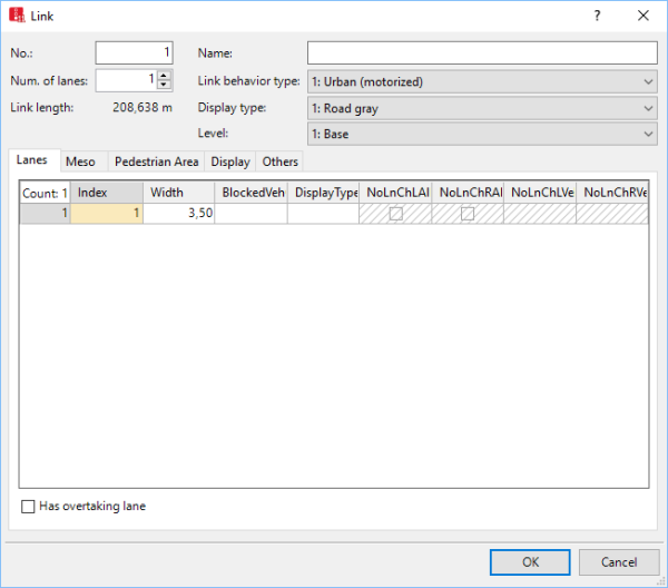
The basic attributes of the network element are shown in the upper area of the window and in the list of network objects for the particular network object type.
| Element | Description |
|---|---|
|
No. |
Unique number of the link |
|
Name |
Designation of the link |
|
Count Lanes |
Number of lanes (NumLanes). The table in the Lanes tab is automatically adjusted. If there already is a lane and you increase the number of lanes, the new lane is inserted in the Network editor and adopts attributes from the existing lane. |
|
Link Length |
Length2D: Length of the link in meters Length3D accounts for z-offset of the link |
|
Behavior type |
Link Behavior Type (LinkBehavType): Driving behavior for the link (Defining link behavior types for links and connectors) and (Defining driving behavior in a driving behavior parameter set). If the attribute Is pedestrian area is selected, the behavior type None is automatically selected. |
|
Display type |
Colored display of the link (Defining display types). In the coupled list Lanes, in the Display Type column, you can edit the Display Type attribute for individual lanes of the link. The coupled list Lanes is selected in the Links list, in the Relations list box. |
|
Level |
For modeling of multistory buildings or bridge structures: level on which the link is located |
|
Has passing lane |
HasOvtLn: The inner lane may only be used for overtaking maneuvers on the oncoming lane. This is only possible on links with at least two lanes (Modeling overtaking maneuvers on the lane of oncoming traffic).
If a passing lane and regular lane of a link of the opposite direction overlap for long enough, the overlapping area may be used for passing. Only select this attribute for links on which passing is actually allowed in reality. Avoid passing lanes on which overtaking is not possible in reality, e.g. at junctions or in traffic controlled areas. You can also select this attribute for several, successive links that are connected via connectors and have at least two lanes. Vehicles can then use the entire overlapping area for overtaking maneuvers. If the passing lane is closed for a vehicle class, the vehicles of this class cannot use the passing lane for overtaking. You can place other network objects, e.g. data collection points, on passing lanes. Passing lanes are not shown in 3D mode. |
The list in the tab contains, amongst others, the following attributes:
| Column | Description |
|---|---|
|
Index |
Unique number of the lane. You cannot change this entry later on. |
|
Width |
Width of the lane If several lanes are defined, several rows are displayed. You can define different widths. The width has an effect on:
|
|
BlockedVehClasses |
Blocked vehicle classes on this lane.
|
|
Display type |
Color of lane (Defining display types) |
|
NoLnChLAllVehTypes, NoLnChRAllVehTypes |
No lane change left – all vehicle types and No lane change right– all vehicle types: |
|
NoLnChLVehClasses, NoLnChRVehClasses |
No lane change left - vehicle classes and No lane change right - vehicle classes: Vehicle classes, whose vehicles must not change from a chosen lane to the adjacent lane in the direction of travel. A prohibition of lane changes is shown in the 2D and 3D mode by means of a solid line. |
|
|
Notes:
The option All Vehicle Types is a virtual vehicle class that automatically includes all new vehicle types and vehicle types that have not been assigned a vehicle class yet. |
Link attributes for mesoscopic simulation:
| Long name | Short name | Description |
|---|---|---|
|
Meso speed model |
MesoSpeedModel |
Specifies how the speed of vehicles on this link is determined.
|
|
Meso speed |
MesoSpeed |
Meso speed is used exclusively in combination with the meso speed model Link related (Car following model for mesoscopic simulation). In this case, the meso speed defines the speed for all vehicles on the link. Default value 50.0 km/h |
|
Meso follow-up time |
MesoFollowUpGap |
Follow-up gap between two vehicles in the same traffic flow. Edit this attribute in the Meso turns list or in the coupled list Nodes - Meso turns (Attributes of meso turns), (Attributes of nodes). |
Attributes of links, if they are meant to be used by pedestrians and not by vehicles:
| LongName | Short name | Description |
|---|---|---|
| Is pedestrian area |
IsPedArea |
Only with Viswalk:  If this option is selected, the link is defined as a pedestrian area (Modeling links as pedestrian areas). If this option is selected, the link is defined as a pedestrian area (Modeling links as pedestrian areas). |
| Pedestrian Behavior section | ||
| Area behavior type | AreaBehavType | Is used to model occasional changes to the speed or other parameter (Modeling area-based walking behavior). |
| Desired speed factor |
|
Factor for changing the desired speed of all pedestrians, default value100 %, value range 10 % to 300 %. Using the desired speed factor, you can reduce the desired speed on the route when pedestrians move slower than at their originally desired speed, for example when walking on bad ground or carefully crossing a road. Using the desired speed factor, you can increase the desired speed on the route when pedestrians move faster than at their originally desired speed, for example when quickly crossing a road. |
| Conflicts with vehicles section | ||
| Consider vehicles in dynamic potential | ConsVehInDynPot |
: For the pedestrian route locations of the pedestrian route leading across the link and for which you have selected the dynamic potential, select a calculation interval that is sufficiently short.(Dynamic potential attributes). |
| G for vehicles | VehDynPotG | Vehicles dynamic potential G: Dynamic potential parameters affecting the general strength of vehicles, default value: 3. This attribute also has an effect on the oncoming lane. |
Attributes for the display of the link. The attributes do not influence the driving behavior.
The tab contains, amongst others, the following attributes:
| Element | Description |
|---|---|
|
3D |
|
|
z-offset (start) |
ZOffset (zOffsetStart): Starting point of z-coordinates of link for 3D display. |
|
z-offset (end) |
z-offset (end) (zOffsetEnd): End poiont of z-coordinates of link for 3D display. |
|
By default, z-offset (start) and z-offset (end) do not have any impact on the driving behavior when it comes to upward or downward gradients. If the z-coordinates in your Vissim network have been entered correctly, you can have Vissim calculate upward and downward gradients. In this case, the option Use gradient from z coordinates must be selected (Selecting network settings for vehicle behavior). If you change the values of the z-offset (start) or the z-offset (end) and have inserted intermediate points into the link, Vissim will recalculate the z-offset values of the intermediate points. To ensure that the upward or downward gradient is harmonious, Vissim calculates a spline for the vertical course of the link. |
|
|
Thickness (3D) |
Thickness for display of the link in 3D mode. |
| Element | Description | ||
|---|---|---|---|
|
Visualization |
|||
|
Individual vehicles |
Show individual vehicles (ShowVeh):
|
||
|
Show classified values |
ShowClsfValues: |
||
|
Label |
|
||
|
Show link bar |
Select this option to to show links with link bars (List of graphic parameters for network objects). |
||
The tab contains, amongst others, the following attributes:
| Element | Description |
|---|---|
|
Gradient |
Uphill and downhill slopes of the link in percent. Downhill slopes have a negative value. The value impacts the driving behavior via the maximum acceleration and maximum deceleration on a link.
Per default, uphill and downhill slopes in 3D mode do not affect the display (z-coordinates) of links. You can edit z-coordinates via the z-Offset attribute. If the z-coordinates in your Vissim network have been entered correctly, you can have Vissim calculate uphill and downhill slopes. In this case, the option Use gradient from z coordinates must be selected (Selecting network settings for vehicle behavior). |
|
Overtake only PT |
OvtOnlyPT: Vehicles traveling on a route with at least two lanes may overtake a stationary public transport vehicle during boarding and alighting of passengers if there is enough space ahead of it. In all other cases, overtaking is not possible. |
| Element | Description |
|---|---|
|
Evaluation |
|
|
Vehicle record |
Vehicle record active (VehRecAct): |
|
Lane changes evaluation active |
LnChgEvalAct: |
|
Link evaluation active |
LinkEvalAct: |
|
Segment length |
The segment length which is taken into account in the link evaluations |
|
Network performance evaluation active |
NetPerfEvalAct: In the network performance evaluation of a micro simulation or a mesoscopic simulation, parking spaces and vehicle inputs are only counted for the output attributes Demand (latent) and Delay (latent), if for their links, Network performance evaluation active is selected. The output attribute Vehicles (arrived) only records vehicles that have driven on a link for which the attribute Network performance evaluation active is selected. In the network performance evaluation of a mesoscopic simulation, the data is used for all meso edges that lead across at least one link for which the attribute Network performance evaluation active is selected. |
In the Dynamic assignment section:
| Element | Description | |
|---|---|---|
|
Cost |
Distance-dependent costs per km (CostPerKm). |
|
|
Surcharge 1 Surcharge 2 |
One-time surcharges that are taken into account for path evaluation. In the dynamic assignment, the costs for the vehicles which travel on this link are determined. |
|
In the Overtaking in the opposing lane:
| Element | Description | |
|---|---|---|
|
Overtaking speed factor: |
OvtSpeedFact: Factor by which the vehicle wants to overtake, increasing its desired speed. Default 1.30. |
|
The following attributes are only relevant for modeling overtaking maneuvers on the oncoming lane:
| Element | Description | |
|---|---|---|
|
Look ahead distance |
Look ahead distance for overtaking (LookAheadDistOvt): Distance that the overtaking vehicle can view on this link, upstream of the oncoming lane. At this distance oncoming traffic is perceived by drivers. At the end of this distance a virtual, oncoming vehicle is assumed, if on this link there is a vehicle input, a PT line or an inbound connector further upstream. The shorter the look ahead distance for overtaking is, the smaller the likelihood of being able to overtake. Default 250 m. |
|
|
Assumed speed of oncoming traffic |
AssumSpeedOncom: Speed of vehicles in oncoming lane in the following situations:
The higher the assumed speed of oncoming traffic is, the smaller the possibility of overtaking in these situations. Default value 60 km/h. If there is an oncoming vehicle within the look ahead distance of the vehicle wishing to overtake, Vissim uses its current speed. |
|
The following attribute is only relevant for matrix correction:
| CountedData (CntData): Shows the count data of the selected vehicle class, if configured in the matrix correction procedure (Correcting demand matrices). |
The attribute and attribute values of this network object type are shown in the list on the left, which consists of two coupled lists.
1. In the list on the left, click the desired entry.
The list on the right contains attributes and attribute values of network objects, and/or base data allocated to the network object selected in the list on the left (Using coupled lists):
2. On the list toolbar, in the Relations list, click the desired entry.
3. Enter the desired data.
The data is allocated.
Superordinate topic:
Modeling links for vehicles and pedestrians
Information on editing:
 If this option is not checked, no vehicles are indicated in the 2D mode. With this, you can indicate underpasses or tunnel sections. This option applies for the entire link. Therefore you must define a separate link for each underpass or for each tunnel.