This analysis method regards approach capacity as a function of geometry and the conflicting volume in roundabouts. On the basis of numerous observations, this function was calibrated to British roundabouts.
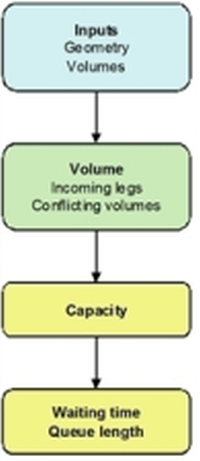
Illustration 77 shows the calculation process for roundabouts according to the TRL/Kimber method.

Illustration 77: Calculation process for roundabouts according to the TRL/Kimber method
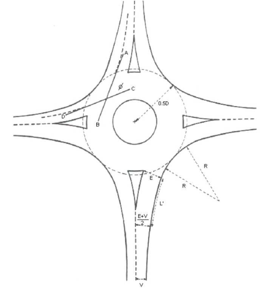
In Visum, the geometry of the roundabout is described through leg attributes. These attributes are only important if the node is a roundabout, and if TRL/Kimber is selected as analysis method. In all other cases, the parameters are ignored at ICA calculation. The meaning of the parameter is illustrated in Illustration 78 which has been taken from the DMRB guideline TD 16/93. For a better comparison with this guideline, the common English original attributes and abbreviations are specified in the tabular overviews. Another parameter describes the temporal variability of the inflow.

Illustration 78: Description of the node geometry for the TRL/Kimber model
Table 118 shows the additional input attributes at legs for calculation according to TRL/Kimber.
|
Name |
DMRB definition |
Value type |
Value range (Default value) |
Meaning |
|
Roundabout inscribed circle diameter |
RoundaboutInscribedDiameter |
Length |
10 - 200 m (40 m) |
External diameter of the roundabout. For asymmetric roundabouts specify the radius related to the environment of the respective approach. The attribute is used during ANM export and ICA (Kimber). |
|
ICA entry width |
ICAEntryWidth (e) |
Length |
3 - 20 m (7 m) |
Width of the entry directly at roundabout |
|
ICA approach half width |
ICAApproachHalfWidth (v) |
Length |
2 - 15 m (3.5 m) |
Road width of the approach link without pocket |
|
ICA flare length |
ICAFlareLength (L‘) |
Length |
1 - 100 m (20 m) |
Half length of the approach between the points where ICAEntryWidth and ICAApproachHalfWidth are measured. |
|
Roundabout entry radius |
RoundaboutEntryRadius (r) |
Length |
1 - 1,000 m (35 m) |
Circle radius which tangentially approximates to the outer circle of the roundabout and the outer boundary of the approach. The attribute is used during ANM export and ICA (Kimber). |
|
ICA entry angle |
ICAEntryAngle (Φ) |
Integer |
0°..180° (45°) |
see Illustration 78 |
|
ICA grade separation |
ICAGradeSeparation (SEP) |
Length |
0 - 100 m (0 m) |
Distance between approach and exit of the same node leg. For regular roundabouts specify 0 m. This implies the roundabout is not grade-separated. With values > 0 you describe the approaches of grade-separated expanded roundabouts, where the entry is far away from the exit of the same leg. |
|
ICA Kimber Hollis c-factor |
ICAKimberHollisC |
Double |
0 .. 10 (1.0) |
In the queue length formula by Kimber-Hollis, the c-factor describes the variability of the inflow |
Table 118: Input attributes for calculation according to the TRL/Kimber method
These attributes are only important if the To-node of the link has the controller type roundabout, i.e. the link represents an approach to a roundabout. In all other cases the attributes are ignored.
The output attributes correspond to those for signalized intersections (Table 101).
Step 1: Traffic flows and conflicting volumes for each approach
All calculations are based on the traffic flows and conflicting volumes at each approach. These traffic flows are derived from the turn volumes. All volumes are expressed in PCUs.
Step 2: Approach capacities
For roundabouts with RDistanceExit = 0, the following applies:

where
|
Cap |
approach capacity in PCU/h |
|
qc |
conflicting flow in PCU/h |
|
k |
1 - 0.00347 • (Φ - 30 ) - 0.978 • [(1/r) - 0.05] |
|
F |
303 x |
|
f |
0.21 t (1 + 0.2 x) |
|
t |
1 + 5 / (1 + M) |
|
M |
e(D - 60)/10 |
|
x |
v + (e - v) / (1 + 2 S) |
|
S |
1.6 (e - v) / L‘ |
The remaining variable descriptions refer to the attributes of the geometry description.
Different from the above mentioned, the following applies for roundabouts with RDistanceExit > 0:
Cap =1.004F - 0.036SEP - 0.232 qc + 14.35 - f qc(2.14 - 0.023 qc)
where all sizes as above, however Cap and qc in PCU/min.
Each turn capacity is based on the capacity calculated for the approach. The result is saved in PCU/h in the turn attribute ICAFinalCapacity.
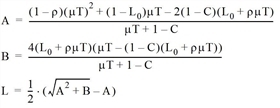
The queue length of an approach results from the Kimber and Hollis formula (Kimber, Hollis 1979), (Kimber, Daly 1986).

where
|
L |
expected queue length at the end of the observation period in PC units |
|
μ |
approach capacity in PCar units/h |
|
T |
length of the observation period in h |
|
L0 |
initial queue length (in Visum always 0) |
|
C |
Variation factor KVKimberHollisC |
|
v |
approach volume in PCar units/h |
|
ρ |
= v / μ = Saturation |
Visum uses the formula modified in (Kimber, Hollis 79) for increased accuracy.
The mean queue length of each turn is equal to the mean queue length of its approach and is saved to the turn attribute ICA mean queue length.
Step 4: Delays
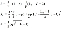
The mean control-based wait time per approach results from the Kimber and Hollis formula (Kimber, Hollis 1979), (Kimber, Daly 1986).

where
|
d |
mean permitted delay in the observation period in h |
|
μ |
approach capacity in PCar units/h |
|
T |
length of the observation period in h |
|
L0 |
initial queue length (in Visum always 0) |
|
C |
Variation factor KVKimberHollisC |
|
v |
approach volume in PCar units/h |
|
ρ |
=v / μ= saturation |
The mean permitted delay of a turn is equal to the mean permitted delay of its approach and is saved in the turn attribute tCur.
As in Step 3, Visum evaluates.the formula modified by Kimber and Hollis for increased accuracy.
Step 5: Level of Service (LOS)
The concept of a LOS is not mentioned in the Kimber model. To create consistency within ICA and because the RFC (Ratio Flow to Capacity) skim was criticized as being insufficient, Visum still defines a LOS per approach as a classification of the mean delay (Table 119).
|
LOS |
Mean Delay [s / PCU] |
|
A |
0 - 10 |
|
B |
>10 - 15 |
|
C |
>15 - 25 |
|
D |
>25 - 35 |
|
E |
>35 - 50 |
|
F |
>50 |
Table 119: LOS for calculation based on the mean delay, according to Kimber
Visum calculates the LOS of the entire node accordingly, on the basis of the volume weighted mean delay of all approaches.

