Connectors connect zones to the link network. Each zone has to be connected to at least one origin zone and one destination connector to the network for the assignment, so that the road users can exit and enter this zone. A zone can be connected to the network with any number of connector nodes.
A connector corresponds to an access or egress route between the zone centroid and the connecting node. A connector has therefore two directions.
Illustrates the access route to the network and thus the first part of the change of location.
Illustrates the egress route from the network and therefore the last part of the change of location.
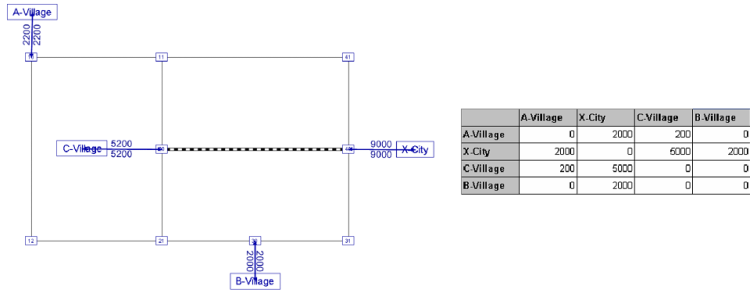
The Illustration 10 shows an example of how the travel demand between the zones, which is saved in the demand matrix, is applied via the connectors to the network.

Illustration 10: Supply of the travel demand via connectors to the network
For each direction, the permitted transport systems, meaning those transport systems which are permitted to use this connector, can be determined. In PrT, connections can be opened for all PrT transport systems. In PuT, however, a path always starts and ends with a route traveled by PuT pedestrian transit system on the connection. It is therefore assumed, that the access and egress of the stop is always by foot. For connectors in PuT there are basically two possibilities of modeling.
- One or more nodes in proximity to the zone centroid are connected. A PuT path always starts and ends with a walk link on the connector and continues on the network links to the access nodes of the next stop area and from there to the stop point, from which a vehicle journey is used (this approach is not recommended).
- Only nodes which are also access nodes of a stop area are connected. In this case, each path starts and ends with a walk link on the connector and within the stop continues to the start stop point. Links are not used like that (this procedure is recommended).
The transport system dependent Connector time in unloaded network t0 is the time which each transport system requires to pass the connector. The default value for t0 per transport system is calculated from the connector length (default value is the direct distance) and the connector speed which also exists as a default value (User Manual: Specifying default values for connectors). The default value for the connector speed can be assigned separately for PuT and PrT connectors. t0 can be overwritten manually.

