1. In the Network editor window, click the Insert mode icon  .
.
2. In the Network window, click the Main nodes button.
3. In the network, click the position where you want to insert the centroid of the main node.
|
Tips: You specify settings for the newly inserted network object directly in the Quick view (Main nodes) window. If you want to display the Create main node window when inserting the object, you can right-click the Main nodes button in the Network window, activate Show dialogs when inserting objects, and directly adjust settings for the newly created network object. The attributes of main nodes are described in the Junction editor chapter (Editing main node attributes in the list view) |
The centroid of the main node is inserted. You can now insert a border and allocate partial nodes to the main node (all nodes with coordinates within the border). The border is optional. It is used for the definition of the partial nodes and main turns via partial nodes (Managing main turns).
You can continue as follows:
- If you do not want to allocate partial nodes to the main node, press the Esc key. The main node is then inserted as centroid without a border. You can define the border and allocate the partial nodes later (Creating a boundary and Allocating nodes to one or multiple main nodes).
- If you want to allocate nodes to the main node as partial nodes, proceed with the next step.
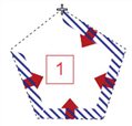
4. Specify the border of the main node by inserting at least three polygon points in a counterclockwise direction in the desired positions.
The edges of the border polygon are displayed as a rubber band. The hatching and the arrows indicate the direction of the face (Fundamentals: The surface data model in Visum).
5. To confirm the definition of the border, press Enter.
The border is created. The partial nodes that lie within the border are allocated to the main node, the main node is inserted in the network and the corresponding main turns are generated automatically (Managing main turns).
