|
Notes: A tooltip is provided for all buttons of the schematic view, which describes the action triggered when clicking the button. Links which are closed in both directions are displayed as dashed lines in the Junction editor if you click Show also closed links on the shortcut menu of the list view. One-way roads are displayed as arrows. |
1. In the network, double-click the node whose links you want to edit.
The Junction editor opens and displays the selected node.
2. Make sure that the Links view is selected in the Views window.
The Junction editor displays all approach links of the selected node.
3. Make the desired changes.
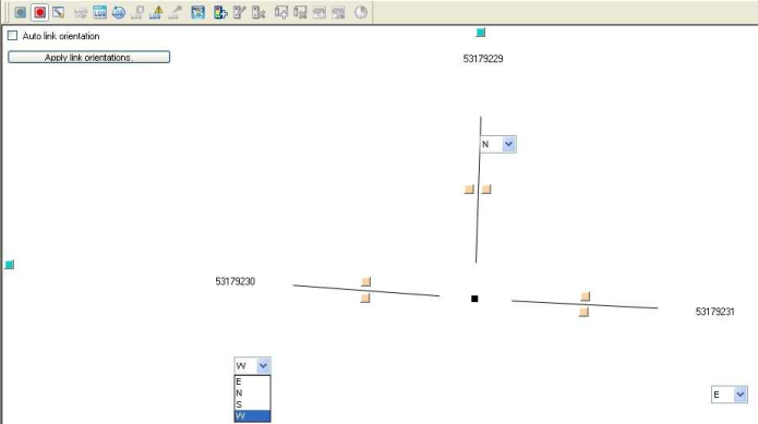
Specifying link orientations
For each link, an orientation can be specified. The orientation of a link can be set automatically or manually.
- ► Make the desired changes in the schematic Links view.
|
Element |
Description |
|
Auto link orientation |
Tip Adjacent one-way streets which point in opposite directions can be given the same orientation and thus be combined in one leg. |
 If the option has been selected, the link orientations are set automatically with default values, depending on the setting under
  If the option has not been selected, you can edit the orientation of each link of the selected node. Next to each link, a drop-down list will then be displayed, in which you can select the desired orientation. The selection depends on the setting under
 4. In the schematic view, click the Apply link orientations button.
The changed link orientations are applied.
|
Notes: The node attribute Use automatic link orientation indicates whether link orientations were calculated automatically. The link attributes From node orientation, From main node orientation, To node orientation and To main node orientation indicate the location in the network, for example W, E, or NW. You can edit these attributes. Based on the link orientations, the calculated direction is displayed in list type Turns and Main turns via the Orientation attribute, for example WW (=from the West to the West). |
Marking a link
You can mark individual links in the schematic view via the colored buttons next to the links.
1. Click the desired button.
The selected link is marked in the list view.
|
Note: You can edit the attributes of the marked link right in the list. |
2. If required, select further links.
|
Note: You can remove markings if you click the button of the respective turn again. |
