|
Note: A tooltip is provided for all buttons of the schematic view, which describes the action triggered when clicking the button. |
1. In the network, double-click the node that you want to edit.
The Junction editor opens and displays the selected node.
2. Make sure that in the Views window the Node view is selected.
3. Make the desired changes.
|
Note: If the node is part of a main node, you can switch to the view of the related main node. |
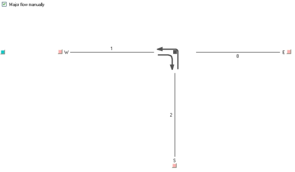
Specifying major flow and link orientations
For nodes with 2 to 8 legs, you can specify a major flow, which describes the course of the priority flow. The major flow of a node can be set automatically or manually.
|
Note: In the schematic view, the major flow is indicated by arrows. |
- ► Make the desired changes to the schematic view of the node.
|
Element |
Description |
|
Major flow manually |
Note Use the option to activate the colored buttons. In this view, you can set the major flow manually by clicking the button of the desired direction.
Note The major flow is determined by the user-defined rank per link type. The highest-ranking links which are connected to the node constitute the major flow. |
 If the option has been selected, the major flow can be set manually.
  If the option has not been selected, the major flow is set automatically.
|
Notes: A major flow cannot refer twice to the same leg of a node or a main node. Adjacent one-way streets which point in opposite directions can be given the same orientation and thus be combined in one leg. The number of legs at a node thus depends on the directions allocated. You can use the Recalculate link orientations function to recalculate the relevant link orientations of the adjacent links after changes have been made for a node (Recalculating link orientations) |
