|
Notes: You can edit the width of the rows and columns by dragging the mouse in the desired direction. You can edit the attribute selection of the list (Adjusting the attribute selection in the Junction editor). Some layout and editing functions can be found in the shortcut menu of the list and the header row. |
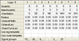
Displaying leg attributes
In the list view, each column describes a leg and each row describes an attribute of this object.
1. Make sure that the Geometry view is selected in the Views window.
2. In the schematic view,
The list view displays all legs of the selected node.
3. Make the desired changes.
Editing leg attributes
You can edit the editable attributes of legs in the list. You can, for example, display the following leg attributes in the list view.
|
Element |
Description |
|
Orientation |
Display of the orientation of the leg |
|
Stop line position |
Position of the stop line, measured as distance from the line of sight Note The entry is relevant when exporting to Vissim. |
|
Center island length |
Length of the center island between the lanes of the two directions of the leg Notes If you want to create a center island, the Center Island Length and the Center Island Width need to be > 0. In addition, the Has Center Island attribute must be selected. The entry is relevant when exporting to Vissim. |
|
Center island width |
Width of the center island between the lanes of the two directions of the leg in meters The entry is relevant when exporting to Vissim. |
|
Channelized turn length |
You can add a channelized turn to the selected leg by entering the desired leg length of the channelized turn between the leg and the separate right turn (left turn for left-hand traffic) originating from it. |
The following attributes are only displayed if you have defined leg templates and geometry templates and the node has signal groups:
|
Element |
Description |
|
Use leg template |
Here you can select a leg template which shall be used for the marked leg. Tip You can create leg templates in a separate window (Creating a leg template). |
|
Apply geometry template |
Here you can select a geometry template which shall be used for the marked leg. Tip You can create geometry templates in a separate window (Creating a geometry template). |
|
Signal groups |
Here you can select the desired signal group for the leg. |
Displaying lane attributes
In the list view, each column describes a main node and each row describes an attribute of this object. Here, for example, you can edit pocket lengths.
1. Make sure that the Geometry view is selected in the Views window.
2. In the schematic view,
The list view displays all lanes of the selected node.
3. Make the desired changes.
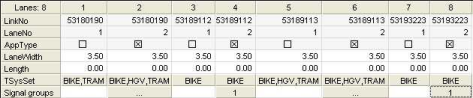
Editing lane attributes
You can edit the editable attributes of the lanes in the list in different ways, depending on the attribute: You can, for example, display the following lane attributes in the list view.
|
Element |
Description |
|
Link number |
Display of the number of the link |
|
Approach type |
Display of the approach type (0 = outflow / 1 = inflow) |
|
Width |
Enter the width of the lane |
|
Length |
Enter the length of the lane |
|
TSys set |
Use the button to select one or more permitted transport systems for the lane in a separate window. |
|
ICA preset saturation flow rate |
Enter the desired saturation flow rate Notes The values of all lanes or a lane group are added. If both turns and lanes exist for a lane group, whose attribute ICA use preset saturation flow rate has been selected, the values of the lanes are used. |
|
ICA use preset saturation flow rate |
If the option has been selected, you can edit the value or the attribute ICA preset saturation flow rate and the specified value is used. |
|
Detectors |
Display of the name of the allocated detector Note This row will only be displayed if detectors are defined. You can allocate one or several detectors to the lane by clicking the corresponding column. Tip Alternatively you can specify the allocation to the lanes directly when inserting the detectors. |
The following properties are always displayed in the list view of the geometry if you select the Lanes option and signal groups are defined:
|
Element |
Description |
|
Signal groups |
Here you can allocate a signal group to the lane. |
Displaying lane attributes
In the list view, each column describes a lane turn and each row describes an attribute of this object.
1. Make sure that the Geometry view is selected in the Views window.
2. In the schematic view,
The list view displays all lane turns of the selected node.
3. Make the desired changes.
Editing lane turn attributes
You can, for example, display the following lane turn attributes in the list view:
|
Element |
Description |
|
From link number |
Number of the link on which the lane turn starts |
|
From lane number |
Number of the lane on which the lane turn starts |
|
To link Number |
Number of the link into which the lane turn leads |
|
To lane number |
Number of the lane into which the lane turns leads |
|
TSys set |
Set of transport systems permitted on this lane turn You can select one or more transport systems for the lane turn. |
The following property is always displayed in the list view of the geometry if you select the Lane turn option and signal groups are defined:
|
Element |
Description |
|
Signal groups |
Here you can select the desired signal group for the lane turn. |
Displaying attributes of crosswalks
In the list view, each column describes a crosswalk and each row describes an attribute of this object.
1. Make sure that the Geometry view is selected in the Views window.
2. In the schematic view,
The list view displays all crosswalks of the selected node.
3. Make the desired changes.
Editing attributes of crosswalks
You can, for example, display the following attributes of crosswalks in the list view:
|
Element |
Description |
|
Orientation |
Orientation of the node leg on which this crosswalk is defined |
|
Width |
Width of the crosswalk |
|
Pedestrian volume |
Pedestrian volume on this crosswalk |
|
Detector |
Long name of the allocated detector Note This row will only be displayed if detectors are defined. You can allocate the desired detector to the crosswalk via a selection list if you click the column. Tip Alternatively you can define the allocation to the crosswalks directly when inserting the detectors. |
The following properties are always displayed in the list view of the geometry if you select the Crosswalks option and signal groups are defined:
|
Element |
Description |
|
Signal group |
Here you can select the desired signal group for the crosswalk. |
Displaying attributes of detectors
In the list view, each column describes a detector and each row describes an attribute of this object.
1. Make sure that the Geometry view is selected in the Views window.
2. In the schematic view,
The list view displays the detectors of the selected node.
3. Make the desired changes.
Editing attributes of detectors
You can, for example, display the following attributes of detectors in the list view:
|
Element |
Description |
|
Number |
Number of the detector |
|
Name |
Long name of the detector |
|
Code |
Code of the detector |
| Lane on link | First lane covered by the detector. |
| Number of lanes on link | Number of lanes of the link observed by the detector, starting with the specified lane in Lane on link |
Allocating signal groups to lane turns or crosswalks
You have to allocate signal groups either to lane turns or to crosswalks so that the signal groups have a spatial reference.
1. Make sure that the Geometry view is selected in the Views window.
2. In the schematic view,
3. Select the desired signal group in the list view under Signal groups.
The signal group is allocated to the lane turn or crosswalk.
|
Note: You can check the allocations of a signal group if you select the Signal groups option in the Geometry view, and open the respective selection window under Lane turns and Crosswalks for the desired signal group (Editing signal group attributes). |
Allocating signal groups to lanes or legs
You can also allocate signal groups to lane turns by allocating them to all lane turns of a leg or lane in one step.
1. Make sure that the Geometry view is selected in the Views window.
2. In the schematic view,
3. Select the desired signal group in the list view under Signal groups.
The signal group is allocated to all lane turns of the selected lane or leg.
Displaying signal group attributes
In the list view, each column describes a signal group and each row describes an attribute of this object.
1. Make sure that the Geometry view is selected in the Views window.
2. In the schematic view,
The list view displays all signal groups of the selected node.
3. Make the desired changes.
Editing signal group attributes
You can, for example, display the following attributes of signal groups in the list view.
|
Element |
Description |
|
Number |
Number of the signal group |
|
Name |
Name of the signal group |
|
Green time start |
Green time start in seconds The green time start and the green time end of the signal group are in the interval [0, round trip time]. The respective value results from the green times of the stages in the case of a stage-based signal controller. If the value 0 is specified as green time start and green time end for a signal group-based signal controller, the signal group shows permanent red, and permanent green for any other but the same value. |
|
Green time end |
Green time end in seconds |
The following properties are always displayed in the list view of the geometry if you select the Signal groups:
|
Element |
Description |
|
Lane turns |
Here you can select the lane turns, which shall be allocated to the signal group. |
|
Crosswalks |
Here you can select the crosswalks, which shall be allocated to the signal group. |
Creating a leg template
You can specify leg templates for the selected node. When using a leg template, a predefined set of lanes, lane turns and crosswalks are generated at a leg.
1. Make sure that the Geometry view is selected in the Views window.
2. In the schematic view,
3. In the list view, right-click the column of the leg that you want to use to specify a leg template.
A shortcut menu opens.
4. Select the entry Marking > Leg template definition.
The Create template window opens.
5. Make the desired changes.
|
Element |
Description |
|
Number |
Number of the leg template |
|
Name |
Name of the leg template |
|
Comment |
Indication of the leg from which the template was created |
6. Confirm with OK.
The leg template is inserted.
Creating a geometry template
Contrary to leg templates, geometry templates can be applied to all legs of the selected node (Fundamentals: Geometries).
1. Make sure that the Geometry view is selected in the Views window.
2. In the schematic view,
3. In the list view, right-click the column of the leg that you want to use to specify a geometry template.
|
Note: The selected leg becomes the reference leg of the geometry template. |
A shortcut menu opens.
4. Select the Marking > Define geometry template entry.
The Create template window opens.
5. Make the desired changes.
|
Element |
Description |
|
Number |
Number of the geometry template |
|
Name |
Name of the geometry template |
|
Comment |
Indication of the node from which the template was created |
6. Confirm with OK.
The geometry template is inserted.
|
Tip: Many actions for selected objects can also be performed using the shortcut menu of the respective list (Lists menu). |
