The network merge function provides for the comparison of two transport networks and the output of their differences. For network merge any networks can be combined with each other. After that, however, only evaluation functions are available, hardly any editing functions.
Use cases for network merge
For project management you want to determine the differences between two Visum models. Occasionally there are two different version files available for one project (for example for different scenarios) and you want to be able to relate to the differences in the two models.
Two variants of one model usually differ in that some attributes of a few network objects have different values. If, for example, you model different expansion statuses of the same network in two version files, there will be deviations in the Number of lanes and Capacity PrT attributes of some links, for instance. Furthermore, network objects can only be in one of the two models and missing completely in the other. If for example, one of the two models contains a planned case with an additional by-pass, the respective links will be missing in the other model.
The following illustrations show both cases. Compared to Network 1, Network 2 contains an additional link. The two networks further have different TSysSet and v0PrT values.
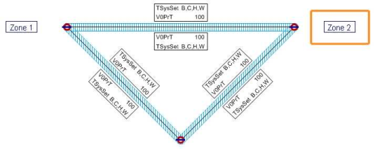
Image 51: Network 1 used for merge network
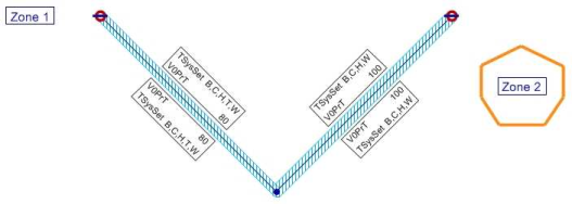
Image 52: Network 2 used for merge network
The merge network
The two models to be compared, network 1 and network 2 have to be available as version files. If you open both version files in the network merge mode, Visum shows a so-called merge network. The merge network is created by first identifying all objects which occur in both models. Two objects are the same if they have identical key attributes. Compulsory references to other network objects (for example, for links the keys 'From Node' and 'To Node') must correspond. Exceeding this intersection of the network objects, objects which only occur in one of the two models are also transferred to the merge network. This is the main difference compared to version comparison. The disadvantage to be put up with is the limited editability.
Additionally, a calculated DIFFNET attribute is created for each network object. It reflects the status of the network object.
- In network 1: Only network 1 contains the object, network 2 does not.
- In network 2: Only network 2 contains the object, network 1 does not.
- DIFF: Network 1 and 2 both contain the object, with at least 1 attribute having different values in both networks.
- EQ: Network 1 and 2 both contain the object, all attributes are identical in both networks.
- In no network: The object exists only in the merge network and has no attribute values.
Example: A turn between a link of network 1 and a link of network 2. Such objects are created in rare cases, so that the merge network is a permissible Visum network. They have no real equivalent and no attribute values.
In the merge network, a read-only attribute is created for each network 1 and/or network 2 attribute (Visum attributes and user-defined attributes). This attribute has the following properties:
- The attribute has identical properties as in network 1 or network 2.
- The attribute has a sub-attribute with values Network1, Network2 and Difference. Network1 and network2 indicate the original attribute values stored with each original network version file if the object is part of the original network version; otherwise, 0 or blank is output.
- The Difference sub-attribute value serves to output the difference and has the following values.
- For numerical attributes, the difference is calculated from Net1 and Net2 data
- For strings, "==" is output in case of identical strings, whereas "<>" indicates deviating strings. Blanks are output for objects which are not part of both original network versions.
|
Note: In case of user-defined attributes with identical IDs but different min/max value ranges, the value range of Net1 will be used. For objects with coordinates, the coordination values are taken from network 1for the display in the network. |
|
Note: Network merge ignores the following objects and settings:
|
The Image 53 displays the merge network of network 1 (Image 51) and network 2 (Image 52).
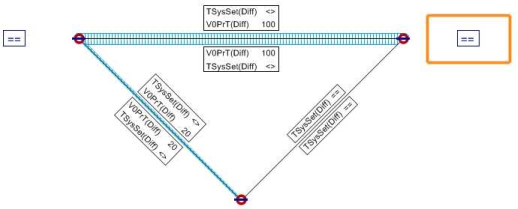
Image 53: Merge network of network 1 and network 2
In the network view of the merge network, you can see that the link at the bottom left of network 2 has a lower speed of about 20 km/h and varies in TSysSet. The link at the bottom right is, however, identical in both networks.
Characteristic: Analysis time intervals
In case of identical analysis time intervals of network 1 and network 2 (ID and interval limits), these intervals are equally stored with the merge network. In case of deviating interval properties, no intervals will be created in the merge network. The conformity of the analysis periods and horizons is not checked. Attribute values which refer to different analysis periods or horizons in network 1 and network 2 will still be stored with the merge network.
