Restricted traffic areas are network objects that allow you to model territories and link sequences with special constraints or restrictions. These include driving bans, through traffic bans, or toll concepts. You can insert restricted traffic areas by defining a polygon. For links within the restricted traffic area, an allocation to the restricted traffic area is automatically made if they are completely within the polygon. For this purpose, the link attribute Restricted traffic area set is assigned with the number. When editing the polygon, the allocation is automatically adjusted. You can also interactively remove or add individual links from a restricted traffic area. This is useful, for example, for large intersections with several levels, when the restriction applies only to one level. If entire zones are to be in the restricted traffic area, make sure that all connectors lead to links that are part of the restricted traffic area. Furthermore, you can define several restricted traffic areas of the same type, which can also overlap (User Manual: Managing restricted traffic areas). This means that links can be assigned to several restricted traffic areas.
In Visum there are different types of restricted traffic areas:
When no traffic is permitted, closed transport systems are not allowed to operate in the territory. This also applies to internal trips within the restricted traffic area. In the case of driving bans, it must be ensured that the assignment matrices for the relations affected by the driving ban do not contain any demand.
Examples of driving bans include environmental zones in Germany, where only vehicles that meet certain emissions standards have access.
Through traffic bans are territories or link sequences where the entry for destination demand / the exit for origin demand is permitted for the transport systems affected by the through traffic ban, but passage through the restricted traffic area is not permitted.
A common example is the ban of HGVs passing through city centers.
The area toll defines a geographically coherent section of the network as a restricted traffic area. A fixed amount is charged per transport system, independent of the distance, provided that part of a route falls into the area:
Examples of area tolls include the Congestion Charging Zone (CCZ) and the Ultra Low Emission Zone (ULEZ) in London.
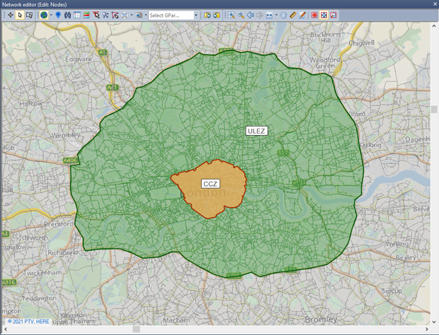
Image 29: Congestion Charging Zone and Ultra Low Emission Zone in London as an example of an area toll
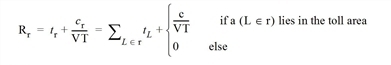
Area tolls impact assignment procedures as part of the impedance in route search and distribution. In addition, the toll and the resulting revenues are determined for each route. The toll is zero for routes that do not touch the toll area. All other routes (origin traffic, destination traffic, through traffic, internal traffic) are charged the toll amount specified for the transport system.
|
For paths that cross the border of the toll area multiple times, the toll amount is charged multiple times. This may not be the case in reality but it cannot be avoided during implementation. Similarly, in reality, the internal traffic of the toll area may be excluded from toll calculations. It is irrelevant for the route choice if these flows are nevertheless charged with tolls because the toll applies equally to all alternatives and does not change the equilibrium solution. However, if you calculate a skim matrix that includes the toll, for example, to use it in the demand model, you must subtract the toll amount yourself in a matrix operation after calculating the skim matrix for the internal traffic OD pairs. |
This type is the typical road pricing scheme for motorway corridors. A subset of links is designated as a toll zone with a small number of connections (entries and exits) to the rest of the network. Toll prices are not defined as a total of link toll prices, but there is an individual price for each pair (entry – exit). Because of these pairs, this type of road pricing scheme is called a matrix toll. Using such a fee matrix, the operator has more flexibility since the toll amounts for longer routes can be defined irrespectively of the toll amounts for shorter sections of a longer route. Toll typically increases with distance but in a degressive way, i.e. the toll per km decreases with distance.
The French motorways are an example of this type of toll.
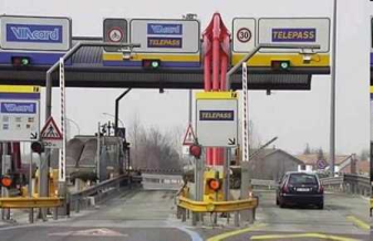
Image 30: Toll station at a highway exit
As a matter of principle, such a matrix toll (which is named according to the fare matrix) cannot be reduced to summing up the toll amounts by link. Let's have a look at the example in Image 31:
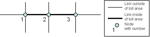
Image 31: Example of a matrix toll
The links 1-2 and 2-3 form a highway corridor with matrix toll. For that, define the toll area first by creating a network object 'Restricted traffic area' of the matrix toll type and then allocating the toll area's number to all links that are located in the area as value for the attribute Toll system number. The restricted traffic area additionally contains a matrix of toll amounts per transport system between all border nodes of the toll area. In our example, these are nodes 1, 2, 3. The toll amounts are listed in Table 10.
|
from / to node |
1 |
2 |
3 |
|
1 |
0 |
2 |
3 |
|
2 |
2 |
0 |
2 |
|
3 |
3 |
2 |
0 |
Please note, that the toll amount for the overall link is less compared to the two individual links.
For each pair (entry, exit) in the restricted traffic area, TRIBUT generates a virtual link with the toll amount from the matrix in the network and uses these virtual links for the shortest path search. In contrast, the original links in the toll area are not regarded for the shortest path search. To determine travel time, the volumes allocated to the virtual links are transferred back to the original links. This allocation is always based on the route with the minimum time (regarding t0) required between 'from node' and 'to node' of the virtual link. Image 32 shows the graph that is generated for the shortest path search in the example.
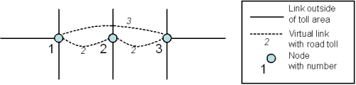
Image 32: Shortest path search graph with matrix toll
This modeling approach assumes a degressive toll matrix, i.e. if there are three nodes A, B, and C, cA-C ≤ cA-B + cB-C always applies. Furthermore, the number of virtual links that are added to the search graph exhibits quadratic growth proportionally to the toll area's number of border nodes. Thus you should use a toll matrix only in those cases where the toll area is connected to the surrounding network by a manageable number of nodes.
|
Note: In addition to matrix and area toll, there is a link toll in Visum that can be defined independently of restricted traffic areas for any PrT transport system on links (Link toll). |
Impact in procedures
The following overview shows which type of restricted traffic areas can be used in which assignment methods:
|
Type |
Considering assignment procedures* |
|
No traffic |
All procedures except DUE and dynamic stochastic assignment |
|
No through traffic |
All procedures except LUCE and TRIBUT assignments |
|
Area toll** |
All procedures except DUE and dynamic stochastic assignment |
|
Matrix toll*** |
TRIBUT-Equilibrium_Lohse |
* When calculating an assignment with ICA, consideration of restricted traffic areas depends on the subordinate assignment.
** For links that belong to a restricted traffic area of the area toll type, the link attribute Toll_PrTSys is taken into account when calculating tolls and revenues. Since in this case, as a rule, only the area toll of the restricted traffic area applies, you must ensure that the link toll for links within this restricted traffic area is zero.
*** For links that belong to a restricted traffic area of the matrix toll type, the link attribute Toll_PrTSys is not taken into account when calculating tolls and revenues.
