The Image 18 shows the six network objects of the line hierarchy.
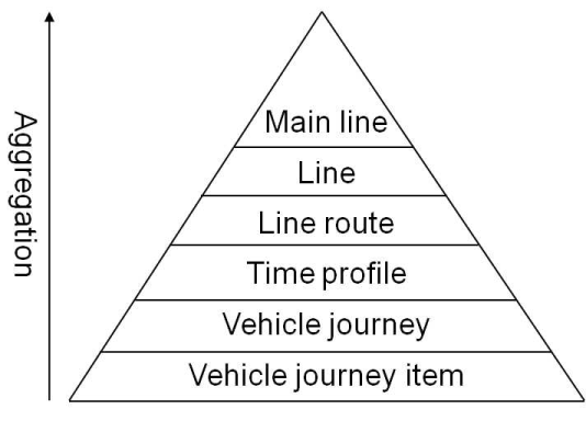
Image 18: The line hierarchy used to model the PuT supply
Main lines
This optional network object is used for an aggregated evaluation of the lines allocated to the main line. A main line can also incorporate lines of different transport systems. The network object does not affect the assignment or the structure of the timetable.
Lines
A line structures the public transport supply. Within the Visum data model, it is mainly used to aggregate several line routes. Each line has at least one line route or multiple line routes. The line itself neither has a spatial course in the network (Line routes), nor are run times specified between the stop points (Time profiles). Each line belongs to exactly one transport system. You can optionally allocate a standard operator and a standard vehicle combination to a line. When creating new vehicle journeys, they will then be suggested as default values.
Line routes
A line route is part of exactly one line and describes the Spatial route course of the line for one direction (from now on called the Line route course).
The line route course is issued as a classified series of route points. The length data of the line route course are output between two consecutive route points. A route point can be a node or a stop point along the line route course. All stop points along the course at which the line route can stop, are always route points. All nodes along the course can optionally be declared as route points. The line route course must start and end at a stop point that is located on a node.
The line routes of a line are usually available in pairs for the two directions. However, each line can incorporate any number of line routes (cf. for example Image 19). Different line routes (pairs) of a line represent different route courses, which are organized in lines.
It is possible to create circle lines where the start stop point is the same as the end stop point and where the onward journey beyond the end stop point is not counted as a transfer (User Manual: Creating a circle line).
Line routes can be generated either manually or based on existing system routes (System routes).
|
Link network |
Line route 1 |
Line route 2 |
|
|
|
|
|
|
||


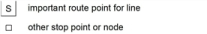
Image 19: Example for two line routes of a line
Time profiles
Each line route has one or more time profiles. A time profile describes the temporal sequence of the line along the line route. However, specific departure times are not specified, but the run times between the individual route points.
Analogous to the line route (route points), the time profile is described by a sequence of profile points. This sequence of profile points is called the course of the time profile. Any route points of the underlying line route can be profile points. However, the start stop point and the end stop point of the line route as well as all stop points, at which passengers can board or alight must be among them. The time profile may also contain passage times for any route points of the line route, e.g. for a conflict check of the timetable routes. Profile points are the points in the network, between which the run times are specified in the time profile. The run time is specified for the section between the previous and the current profile point. In case of stop points, a stop time can additionally be specified and boarding and alighting can be permitted or prohibited.
Multiple time profiles of a line route can, for example, differ in the selection of the profile points or the run times on the different sections between the profile points (cf. for example Image 20). If a vehicle journey of a line route shall stop at a stop point along the route yet another one shall not stop, you need to define two time profiles for the same line route (yet not if a vehicle journey shall serve just a section of the line route and thus of the time profile).
Furthermore, each time profile has a name and an allocation to a direction. Optionally, a standard vehicle combination can be allocated to the time profile. When inserting a new vehicle journey, this is then applied automatically as a default value.
|
Note: Please note that the vehicle combinations of existing vehicle journeys are not overwritten. If a standard vehicle combination is specified for the line also, the standard vehicle combination of the time profile takes effect when inserting a new vehicle journey. |
Fare points can still be specified at the time profile, for each profile point. These can enter the calculation of revenues (User Manual: Settings for the PuT operator model).
For headway-based PuT modeling, the relevant headways are defined on time profile level during headway-based assignment (User Manual: Headway-based assignment).
As a consequence, all network objects which in the line hierarchy are located below the time profiles (vehicle journeys and vehicle journey sections) are not relevant when you define headways. Therefore, if you want to define individual headways, you need to create a separate time profile for the respective vehicle journeys and define the headways there.
|
Line route 1 |
Time profile 1.1 |
Time profile 1.2 |
||||||
|
|
SPoint |
Stop |
Arr |
Dep. |
SPoint |
Stop |
Arr |
Dep. |
|
M |
|
|
12:00:00 a.m. |
M |
|
|
12:00:00 a.m. |
|
|
I |
|
1:00 |
1:02 |
I |
|
- |
- |
|
|
N |
|
2:00 |
2:02 |
N |
|
1:50 |
1:52 |
|
|
W |
|
3:00 |
3:02 |
W |
|
2:50 |
2:52 |
|
|
H |
|
5:00 |
5:02 |
H |
|
4:50 |
5:02 |
|
|
S |
|
6:00 |
|
S |
|
6:00 |
|
|
|
|
|
|||||||


Image 20: Example of two time profiles of a line route
Vehicle journeys (=journeys)
A vehicle journey describes a planned public transport service or a set of planned service trips, which are summarized to an administrative unit with a given ID number. Every day of the calendar used in the network, at most one of these vehicle journeys will then run.
Each vehicle journey belongs to exactly one line route and exactly one time profile. It also has a reference to two stop points of the line route, which define the section on which the vehicle journey follows the course of the line route. Vehicle journeys can therefore traverse any section of a line route. It is therefore not necessary to define a line route with a shorter extension for vehicle journeys, which only traverse a line route partially. Vehicle journeys cannot, however, switch from one line route to another. This means that each trip can only run on exactly one line route.
Furthermore, the vehicle journey contains a departure time at the start stop point from which, together with the relative times of the time profile, all arrival, departure and non-stop run times of the vehicle journey are determined.
A vehicle journey can optionally be assigned an operator. You can then calculate aggregated evaluations of PuT operating indicators on operator level (Operator model PuT).
Vehicle journey sections (=journey sections)
There is normally exactly one journey section per vehicle journey. This is created automatically when inserting a vehicle journey. As an option, a vehicle journey can be subdivided into multiple vehicle journey sections, which can then be divided into the following properties.
- Valid day
- Vehicle combination
- Start and end stop point
- Pre and post preparation time for line blocking (Line blocking)
This results in the following application possibilities for example.
- A vehicle journey, which traverses from A to C via B from Monday to Friday, on the weekend however, only from A to B, can be modeled by two vehicle journey sections, which only differ in their valid days.
- A train, running from A via B to C, between A and B however with less coaches, can be modeled by two vehicle journey sections, which differ in their vehicle combinations and start and end stop points.
- Any combinations are possible, for example a train which runs between A and B and which is only short on the weekend.
- Vehicle journey sections are network objects, with which line blocking is carried out (Line blocking).
The Table 6 shows an example with three vehicle journeys of a line route. The line route has two time profiles. Vehicle journey 993 is divided into three vehicle journey sections, which differ in valid days and vehicle combinations.
|
Trip number |
from -> to |
Departure time |
Valid day |
Vehicle combination |
|
991 |
N ⇒ H |
06:02 a.m. (daily) |
Daily |
Loco + 6 coaches |
|
992 |
M ⇒ H |
05:10 a.m. (daily) |
Daily |
Loco + 6 coaches |
|
993 |
M ⇒ H |
06:00 a.m. (daily) |
Daily |
Loco + 6 coaches |
|
H ⇒ S |
11:02 a.m. (Sat+Sun) |
Sat+Sun |
Loco + 6 coaches |
|
|
M ⇒ N |
06:00 a.m. (Mon-Fri) |
Mon-Fri |
1 additional coach |
|
Line |
IC1 |
IC1 |
IC1 |
|||
|
Line route |
1 |
1 |
1 |
|||
|
Time profile |
1.1 |
1.2 |
1.1 |
|||
|
Trip number |
991 |
992 |
993 |
|||
|
Valid day |
Daily |
Daily |
- |
Mon-Fri |
Sat+Sun |
Mon-Fri |
|
Vehicle combination |
L+6C |
L+6C |
- |
L+6C |
L+6C |
1C |
|
M dep. |
- |
05:10 a.m. |
06:00 a.m. |
· |
· |
· |
|
I arr. |
- |
| |
07:00 a.m. |
· |
· |
· |
|
I dep. |
- |
| |
07:02 a.m. |
· |
· |
· |
|
N arr. |
- |
07:00 a.m. |
08:00 a.m. |
· |
· |
· |
|
N dep. |
06:02 a.m. |
07:02 a.m. |
08:02 a.m. |
· |
· |
· |
|
W arr. |
07.00 a.m. |
08:00 a.m. |
09:00 a.m. |
· |
· |
- |
|
W dep. |
07:02 a.m. |
08:02 a.m. |
09:02 a.m. |
· |
· |
- |
|
H arr. |
09:00 a.m. |
10:00 a.m. |
11:00 a.m. |
· |
· |
- |
|
H dep. |
- |
|
11:02 a.m. |
- |
· |
- |
|
S arr. |
- |
|
12:00 a.m. |
- |
· |
- |
|
||||||
