Because the vehicles can only move within the modeled network, a stop point has to be connected to the network. This is achieved, by either inserting a stop point on a link or on a node. If a stop point is on a link, it is called a link stop point. A stop point on a node can be supplied by all lines which traverse this node. A stop point on a link can only be served by lines which pass this link. This permits detailed direction modeling based on masts. Stop point links can, however, also be inserted undirected, so that they can be run for both directions of the link.
|
|
|
|
Stop point on node |
Link stop points |
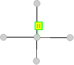

Image 17: Possibilities of modeling stop points
The differentiation between stop points on nodes and links allows network models of different levels of detail to be generated with Visum:
- For strategic planning, stop points on nodes are sufficient, since the exact position of the stop point – in front of or behind the road junction – is usually of no interest. The stop area and stop are generated automatically in the background, but generally remain hidden to the user, if desired.
- For operational planning and AVLS supply, it is useful to model the stop points on links, as you can then achieve the required degree of detail.
It is also possible, of course, to mix both types in Visum, for example by using the more accurate link-based model in built-up areas and the node-based model in non-built-up areas.
A stop point can be permitted or blocked for each existing transport system. Only line route vehicle journeys, whose transport system is permitted, can stop there.
|
Notes: We recommend to set the start or end point of a line route only at stop points which are located on nodes, because inaccurate results might occur if a line route starts or ends at link stop points, for example, when calculating PuT operational indicators or in case of PuT volumes which are displayed on link level. Because vehicle journey stops always occur at a stop point, each stop has to have at least one stop point. |
