In the schematic geometry view, you can edit the geometry of nodes or main nodes and connected objects in a variety of ways.
1. In the network, double-click the node or main node that you want to edit.
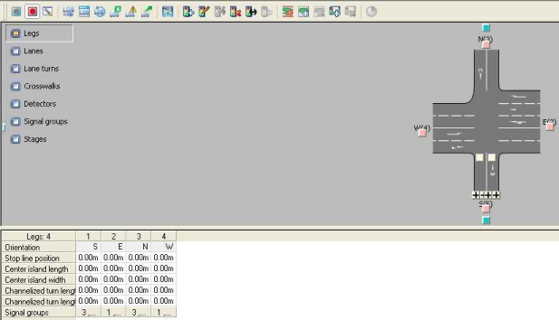
The Junction editor opens and displays the selected node or main node.
2. Make sure that the Geometry view is selected in the Views window.
The node is displayed in the Geometry view.
3. Make the desired changes.
|
Note: The Signal groups and Stages options are only displayed in the schematic view if signal groups or stages have been created. |
