When importing shape files, the information contained in shape files is read in a Visum network. Which network it is imported to depends on the type of shape file (point, line or polygon) and by which processing mode (additive or non-additive). An overview on which shape file types are imported to which network objects is provided by Table 279.
|
|
Link, Screenline, Connector |
Zone, Main zone, Territory, Main node |
Node, Detector, Count location, Stop, Stop point |
Points of interest |
|
Point |
|
X |
X |
X |
|
Polyline |
X |
|
|
X |
|
Polygon |
|
X |
|
X |
|
Note: Creating POIs is only possible with additive reading of shape files, because a POI category has to be specified, where the POIs can be included. At least one POI category has to therefore be contained in the network, to read shape files as POIs. Connectors, stop points, and count locations can only be read in additively. |
To import point objects in shapefile shape format, you must first read them in as nodes and then use the "Aggregate isolated nodes" function to create stop points. In doing so, you also create the corresponding stop areas and stops (User Manual: Aggregating isolated nodes).
While reading polylines as links, you can create alternative directed links or links with both directions. If a link is undirected, it has to be determined how to interpret each attribute.
- Forward: direction from node ... To node
- Backward: direction to node ... From node
- Undir. value: 50% of the value for each direction
- Symmetrical: equal value for both directions
While importing the shape file you can determine which source attribute (from the shape file) should be assigned to which target attribute (an existing or user-defined attribute of the selected network object). The Image 220 shows an example, where shape file data is read as a link. The shape file contains the attributes STREET_NAM, LENGTH and LANE, which allocate the Visum link attributes Name, Length and Number of lanes.
|
Note: When loading polygons from shape files (e.g. as zone polygons or POIs for a background image), you can optionally activate normalization of the loaded surface data (Multi-part surfaces). This is required if you want to use the loaded polygons to perform geometrical operations, such as surface calculation or intersections, as otherwise the results might be falsified. If you merely wish to display polygons, then normalization is not required. |
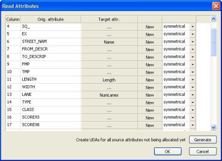
Image 220: Source and target attribute allocations
Example applications
- Reading shape files with a road network as links in Visum. In Visum a routing-enabled link network is then available.
|
Note: The links have to first be enabled for transport systems. |
- Reading cross-communities as territories
- Reading schools as POIs
- Reading land use as POIs
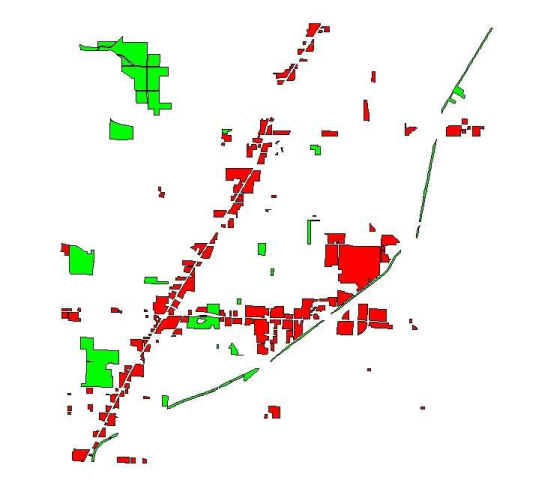
In addition to the import of shape files as Visum network objects, you can also insert shape files as background. This is how you can insert land use (for example residential areas, industrial areas, commercial areas) to make your network more visible, for example. You can thus insert multiple shape file layers into the network (for example a layer for industrial areas). The drawing order of the layers and its color can be changed. The Image 221 shows an example, where two shape files were integrated as a background with land use for residential and commercial areas.