The graph used for simulation consists of nodes and edges. In general, the nodes in the graph correspond to the nodes in the network. However, zones are also represented by nodes in the graph. Edges are either within a node (turn edges) or between nodes (link edges). Link edges basically correspond to the connectors and links of the network. Link edges are generally characterized by the attributes of the respective link (e.g. number of lanes, v0). By default, the length of turn edges within a node is zero. In the example presented (Image 144), the edges of the graph correspond to Visum network objects, e.g. the length of the link edge corresponds to the length of the Visum link.
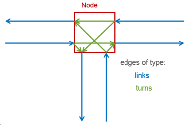
Image 144: Node-edge graph for Visum nodes with standard geometry
This standard case does not apply should node geometry and standard geometry differ, e.g. when there are pocket lanes, channelized turns or roundabouts. In these cases, additional nodes and edges are generated for the graph in Visum. In the following example Image 145 this is shown for pocket lanes at the inbound and/or outbound link. The additionally created nodes and edges of the graph cause the edges allocated to the Visum link and Visum turn to change. In this case, the link edges with two lanes between the nodes in the graph correspond to the Visumturn. The length of the Visum turn (attribute SBA length) is determined by the pocket length. The length of the links (attribute SBA length < length) is reduced accordingly.
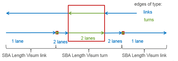
Image 145: Node-edge graph for Visum nodes with pocket lanes
Table 148 contains attributes of node geometry used to create additional nodes in the node-edge graph for simulation.
|
Object |
Parameters |
Meaning |
Control type affected |
|---|---|---|---|
|
Leg |
Is Channelized |
Defines existence of a channelized turn |
All except roundabout |
|
Leg |
Channelized control |
Determines conflict and values of default parameters at end of the separate right turn |
All except roundabout |
|
Leg |
Channelized turn length |
Defines length of channelized turn |
All except roundabout |
|
Leg |
Has bypass lane |
Defines existence of bypass |
Roundabout |
|
Leg |
Bypass control |
Determines conflict and values of default parameters at end of the bypass |
Roundabout |
|
Leg |
Bypass radius |
Determines geometry of bypass |
Roundabout |
|
Leg |
Roundabout inscribed circle diameter |
Determines roundabout geometry |
Roundabout |
|
Leg |
Number of conflicting lanes |
Determines conflicts for the leg |
Roundabout |
|
Nodes |
Roundabout circulating lane width |
Determines roundabout geometry |
Roundabout |
|
Lane |
Length |
Defines length of pocket lane |
All |
Table 148: Additional input attributes for node modeling
From the input parameters, in particular, from the inputs of the node geometry, the length of link and turn edges of the graph are calculated and transferred to the allocated Visum network objects. This allocation has an impact on the allocation of output attributes. For example, travel times and delays can only occur at turns with a length greater than zero. If there is no pocket lane at a signal-controlled node, delays through the signal controller are only indicated at inbound links.
|
Object |
Parameters |
Meaning |
|
Links / (main) turns |
SBA length |
Length of total of edges allocated to the Visum link and or (main)turn |
|
Links |
SBA capacity-PrTSys |
Capacity calculated from the parameters of the car following model of TSys and max.link speed SBA Cap-PrTSys = (3600/temporal headway) x number of lanes with temp. headway = reaction timeTSys x factorLink + (eff. veh. lengthTSys) x factorLink/v0-PrTSys) |
Table 149: Attributes calculated from the node-edge graph
