For pure split optimization, the cycle time is considered to be fixed.
Split optimization for stage-based signal controllers
The following steps are necessary for calculating the green time split:
1. Deconstruct approaches into lane groups (already calculated for capacity analysis).
2. Calculate the adjusted volume and saturation flow rate for each lane group (already calculated for capacity analysis).
3. For each stage in the signal timing plan, determine the critical lane group.
4. Allocate green time based on critical lane group volume/saturation flow rate ratios.
5. Check that the allocated green times meet all the constraints.
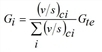
The green time split is calculated as follows:
where
|
Gi |
effective green time for stage i |
|
(v/s)ci |
ratio of volume v and saturation flow rate s for critical lane group ci in stage i |
|
Gte |
total effective green time for cycle |
The total effective green time for a cycle is the same as the cycle time deducting all intergreens between consecutive stages. The intergreen between two stages is zero if the stages share signal groups. Otherwise, intergreen is indicated by the attribute Default intergreen of the signal controller.
Each stage must also maintain the minimum green time, which is given by the Minimum green time attribute of the signal controller. If the calculated green time for a stage is less than the minimum green time, then the green time split equation is rerun with the stage below its minimum green time omitted. The omitted stage is assigned the minimum green time. That minimum green is subtracted from the total effective green time and the green time split is recalculated.
As a result of optimization, new values are assigned to the attributes Green time start and Green time end of the stages.
Green time optimization for signal group-based signal controllers
The optimization of signal group-based signal controllers results from the following steps of the procedure for stage-based signal programs:
A signal group-based signal program must be set for the signal controller. The optimization of signal group-based signal programs results from the following steps of the procedure for stage-based signal programs:
1.
Visum first defines set T of all switching points from the attributes Green time start and Green time end of all signal groups and sorts these in ascending order. For each interval between consecutive times ti and ti+1 in T a stage is generated containing all signal groups available during [ti ; ti+1).
2. The fictitious stage-based signal controller is optimized as above (Split optimization for stage-based signal controllers).
3. The signal group green times are read from the optimal stage distribution.
The green time of each signal group results from the green times of all stages containing the signal group. Since by design all these stages are adjacent, this results in a single green time for the signal group.
4. An ICA calculation is performed for the signal program. This results in
a. the division of approaches into lane groups
b. the adjusted volume and the saturation flow rate for each lane group
5. The critical lane group is determined for each internal stage in the signal program.
6. Allocate green time based on critical lane group volume and saturation flow rate ratios.
The green time split is calculated as follows:
where
|
Gi |
effective green time for stage i |
|
(v/s)ci |
ratio of volume v and saturation flow rate s for critical lane group ci in stage i |
|
Gte |
total effective green time for cycle |
The total effective green time for a cycle is the same as the cycle time deducting all intergreens between consecutive stages. The intergreen between two stages is zero if the stages share signal groups. Otherwise, the intergreen is given by the intergreens of the signal groups.
7. If the overall mean wait time has not improved, cancel and go to 6, otherwise repeat steps 2 to 4 (max. 10 times).
8. The green times of the signal groups are taken from the optimal green times of the stages.
The green time of each signal group results from the green times of all stages containing the signal group. Since by design all these stages are adjacent, this results in a single green time for the signal group.
Green time optimization for signal group-based programs in which signal groups have a second green time is not possible.
Green time optimization for external signal controllers and RBC
Visum can be used to optimize Vissig signal controllers. Stages have to be defined for this signal controller. Optimization of non-stage-based Vissig controllers or controllers of the RBC type will be made available later.
To exclude selected stages from the optimization to keep their lengths as set in the original signal timing plan, select 'true' for the attribute Pseudo stage of these stages.
Visum executes the following steps to calculate the green time split:
1. With the current signal timing plan, execute an ICA calculation and determine both saturation flow rate and volume for each lane group.
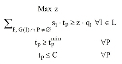
2. Solve the linear optimization problem:
where
|
L |
set of all lane groups |
|
C |
cycle time |
|
sl |
saturation flow rate of lane group l |
|
ql |
volume of lane group l |
|
tP |
green time duration of stage P |
|
|
|

3. Carry out another ICA calculation for the optimized signal program.
4. If the total mean wait time has not improved, cancel the calculation and continue with step 5. If the saturation flow rates have changed, go to 2. Otherwise also go to 5.
5. Assign the Green time start and Green time end attributes of the stages the values of the latest optimum solution.
