Two-way Stop, All-way Stop, and Two-Way Yield Intersection Setup
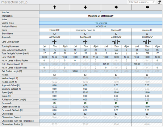
The Intersection Setup table for Two-way stop intersections is shown in the figure of the table below. The tables for All-way stop and Two-way yield intersections consists of identical rows.
Table definitions are presented in the table below the figure Intersection Setup: Signalized Intersection Table. Common parameters are described in a separate chapter (see section Common Parameters and Unknown Control Type).
Figure 8: Intersection Setup: Two-way stop, All-way stop, and Two-Way yield Intersection Setup Tables

The intersection setup tables for the all-way stop, two-way stop and Two-way yield control types include all of the common parameters listed for the unknown control type, plus the parameters listed in the table below:
Table 5: Intersection Setup: Two-way sto, All-way stop, and Two-way yield Intersection Setup Parameters also lists for each parameter if applicable, units, default values, value ranges, relevant unsignalized methodology (HCM 6th Edition, HCM 2010 or HCM 2000), and ANM if the parameter is used when exporting to Vissim.
Table 4: Intersection Setup: Two-way & All-way Stop Intersection Setup Parameters
| Parameter | Description | Units | 6th, 7th Ed. | 2010 | 2000 | ANM | ||
|---|---|---|---|---|---|---|---|---|
|
Analysis Method |
Intersection capacity analysis methodology for selected intersection based on control type. If a global analysis methodology is defined under the global parameters dialog, then the analysis method in the intersection setup table does not apply. [All-way & Two-way Stop options: HCM 7th Edition, HCM 6th Edition, HCM 2010, HCM 2000] |
|
|
|
|
|
||
|
Lane Width |
Width of the travel lane Default = 12 ft (3.7 m), Range = any number |
ft or m |
x |
x |
x |
x |
||
|
No. of Lanes in Pocket |
Defines how many lanes of the approach geometry are pocket lanes. A pocket lane is a lane added on the approach of an intersection. Pocket lanes are most commonly used for turning movements, but may be used for through movements, as well. The pocket lanes are always defined to either the left or right of the through movement. For the example case of a two-lane road with the approach lane geometry of a 1-Left, 2-Thru, 1-Right, there would be 1 pocket lane defined each for the left and right lanes. In a more complex example, a two-lane road with the approach lane geometry of 1-Left, 3-Thru, 1-Right, there would be 1 pocket lane for the left and 2 pocket lanes to the right. Pockets will consider through lanes, if the number of pocket lanes are higher than the number of left or right turn lanes. Default = 0. Range = 0 – [# turn+through lanes – 1] |
|
x |
x |
x |
x |
||
|
Entry Pocket Length |
Length of the respective pocket lane(s) Default = 0. Range = 0 – approach link length. |
ft or m |
x |
x |
x |
x |
||
| No. of Lanes in Exit Pocket |
Defines how many outbound Exit Pockets are on the leg. Exit pockets can be used to define lane drop or downstream tapers, most commonly used for dual-left turn lanes or on through lanes. Pockets can be defined left or right of the thru movement or as inside or outside exit pockets. Exit pockets will automatically be added when intersection legs are connected. Default =0. Range = 0 – [number of exit lanes -1] |
x |
||||||
| Exit Pocket Length | Length of the respective pocket lane(s) Default = 0. Range = 0 – exit link length. | ft or m |
x |
|||||
|
Median |
A checked box defines a center median for the approach. A median is an additional dividing separation between opposing directions on an approach. |
|
|
|
|
x |
||
|
Median Length |
Length of the median for the selected approach measured upstream from the stop bar location. Default = 0. Range = 0 – approach link length |
ft or m |
|
|
|
x |
||
|
Median width |
Width of median for selected approach. A median is an additional dividing separation between opposing directions on an approach. Example (for right-handed driving): If an approach has a 6 ft median width entered and the approach also has one 12 ft left-turn pocket defined, then a 6 ft median will be placed adjacent to the left lane, and would open to an 18 ft median at the end of the left turn pocket.
Default = 0. Range = 0 – any real number |
ft or m |
|
|
|
x |
||
| Approach Offset |
Defines the leg's approach offset to the center of the intersection in the direction of the legs’s approach direction. A positive value shifts the offset to the right and a negative value shifts the offset to the left. Default = 0. Range = -1000 – +1000 |
ft or m |
x |
|||||
| Stop Line Setback |
Defines the position of the stop line relative to the default position from the crosswalk. Positive and negative values can be entered to move the stop line.
|
ft or m | x | |||||
|
Speed |
Speed of selected approach Default = 30 mph (48.3 km/h). Range = 1 - 255 |
mph or km/h |
|
|
|
x |
||
|
Grade |
Grade (slope) of the selected approach Default = 0. Range = 0.00 – 100.00 |
% |
x |
x |
x |
x |
||
| Radius Corner Curb |
Corner radius is visualized in the Network Editor.
|
ft or m | x | |||||
|
Crosswalk |
A checked box defines a crosswalk on the selected approach |
|
|
|
x |
|||
|
Crosswalk Width |
Width of the crosswalk visualized in PTV Vistro. This parameter is used if exporting to Vissim. In Vissim the crosswalks are modeled using two opposing links, so each link has half the width of the full crosswalk width. A crosswalk with of 5 ft will generate a 10 ft crosswalk after exporting to Vissim. Default = 6 ft (1.8 m) Range = 0 – any real number |
ft or m |
|
|
x |
|||
|
Channelized |
A checked box defines a channelized right turn lane (left turn for left-hand model) for the approach. |
|
|
|
x |
|||
|
Channelized Control |
For a channelized turn lane, defines the control for entering the mainline traffic. Options: SC (Signal Control), Stop, Yield, Target Lane (free) |
|
|
|
x |
|||
|
Channelized Radius |
Radius of the channelized turn that tangentially approximates to the outer boundary of the two approaches of the turn movement. Default = 20 ft. Range = 0 – approach link length |
ft or m |
|
|
x |

