Network Optimization Settings
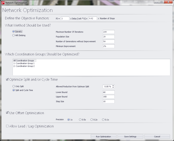
After selecting the desired method for optimization, you can then set various parameters to define the Network Optimization. These options are shown in the figure below:
Figure 40: Network Optimization Settings
Coordination Groups
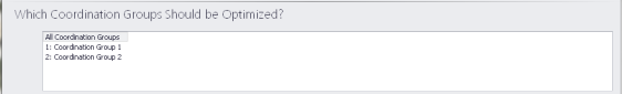
Here the user can select from a drop-down list which coordination groups he wants to be optimized. The drop-down list contains all coordination groups that exist (per definition at the SC in the traffic control tab).
Selection of multiple coordination groups is possible. The selected groups show up as a comma separated list in the closed drop-down menu if this is easy to implement. If it is hard to implement, the selection can just be a persistent selection/marking of the selected groups that is visible if the user opens the drop-down list.
Optimization is carried out for each coordination group separately, i.e. cycle times can be different for different coordination groups.
Split optimization
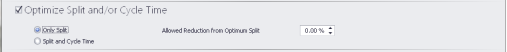
The user can select optimization of only Splits (no Cycle Time Optimization). The user can then define the percent of reduction from the optimum split that would be allowed during the optimization process. No further parameters defined here. The constraints (minGreen etc.) are taken as defined in the Traffic Control tab. Split Optimization only works for cycle times greater or equal the minimum cycle time.
Cycle time optimization
![]()
If the user selects Split and Cycle Time Optimization, then they define a range of cycle times that are optimized.
The user inputs the following:
- Lower boundary cycle time
- Upper boundary cycle time
- Step size (any integer)
The lower boundary is tested, every increment using the step size, and finally the upper boundary (even if the given step size would not find this upper boundary).
Half cycles are always allowed. PTV Vistro retains the relation of the cycle times in a coordination group throughout the cycle time optimization. If a controller has a half cycle before the optimization, it will have a half cycle after the optimization. The Lower Bound and the Upper Bound parameters refer to full cycles. If, for example, Lower Bound and Upper Bound are set to 60 s and 240 s, respectively, half cycles between 30 s and 120 s will be used.
Offset optimization

The user can specify the precision to be applied when searching for the optimum offsets. The user can choose between 1 s, 0.5 s, 0.2 s and 0.1 s. Generally, lower values are more precise but will make the optimization more complex and hence more time intensive.
Allow Lead/Lag Optimization

If Lead/Lag optimization is allowed, then for every signal group combination that allows (as defined in the Traffic Control tab) for Lead/Lag optimization, Leading and Lagging green phases are tested.
