|
Analysis Method
|
Intersection capacity analysis methodology for selected intersection based on control type.
Signalized options: HCM 7th Edition, HCM 6th Edition, HCM 2010, ICU1, ICU2, Circular 212 Planning, Circular 212 Operations, HCM 2000, Canadian Capacity Guide (CCG)
|
|
|
|
|
|
|
|
|
|
Lane Width
|
Width of the travel lane
Default = 12 ft (3.7 m), Range = any number
|
ft or m
|
x
|
x
|
x
|
x
|
x
|
x
|
x
|
|
No. of Lanes in Entry Pocket
|
Defines how many lanes of the approach geometry are pocket lanes. A pocket lane is a lane added on the approach of an intersection. Pocket lanes are most commonly used for turning movements, but may be used for through movements, as well. The pocket lanes are always defined to either the left or right of the through movement. For the example case of a two-lane road with the approach lane geometry of a 1-Left, 2-Thru, 1-Right, there would be 1 pocket lane defined each for the left and right lanes. In a more complex example, a two-lane road with the approach lane geometry of 1-Left, 3-Thru, 1-Right, there would be 1 pocket lane for the left and 2 pocket lanes to the right.
Default = 0. Range = 0 – [# turn+through lanes – 1]
|
|
x
|
x
|
x
|
x
|
x
|
x
|
x
|
| Entry Pocket Length |
Length of the respective pocket lane(s)
Default = 0. Range = 0 – entry link length. |
ft or m |
|
|
|
|
|
|
x |
| No. of Lanes in Exit Pocket |
Defines how many outbound Exit Pockets are on the leg. Exit pockets can be used to define lane drop or downstream tapers, most commonly used for dual-left turn lanes or on through lanes. Pockets can be defined left or right of the thru movement or as inside or outside exit pockets. Exit pockets will automatically be added when intersection legs are connected.
Default =0. Range = 0 – [number of exit lanes -1]
|
|
|
|
|
|
|
|
x |
| Exit Pocket Length |
Length of the respective pocket lane(s)
Default = 0. Range = 0 – exit link length. |
ft or m |
|
|
|
|
|
|
x |
|
Median
|
A checked box defines a center median for the approach. A median is a dividing separation between opposing directions on an approach.
|
|
|
|
|
|
|
|
x
|
|
Median Length
|
Length of the median for the selected approach measured upstream from the stop bar location.
Default = 0. Range = 0 – approach link length
|
ft or m
|
|
|
|
|
|
|
x
|
|
Median Width
|
Width of median for selected approach
Default = 0. Range = 0 – any real number
|
ft or m
|
|
|
|
|
|
|
x
|
| Offset |
Defines the leg’s approach offset to the center of the intersection in the direction of the legs’s approach direction. A positive value shifts the offset to the right and a negative value shifts the offset to the left.
Default = 0. Range = -1000 – +1000
|
ft or m |
|
|
|
|
|
|
x |
|
Speed
|
Speed of selected approach
Default = 30 mph (48.3 km/h). Range = 1 - 255
|
mph or km/h
|
x
|
x
|
x
|
|
|
|
x
|
|
Grade
|
Grade (slope) of the selected approach
Default = 0. Range = 0.00 – 100.00
|
%
|
x
|
x
|
x
|
|
|
x
|
x
|
|
W_cd, Curb-to-Curb Width of the Cross Street
|
Curb-to-curb width of the cross street (used for bicycle analysis with HCM since 6th Edition).
|
ft or m
|
x
|
|
|
|
|
|
|
|
W_bl, Width of the Bike Lane
|
Width of the bicycle lane (used for bicycle analysis with HCM since 6th Edition).
|
ft or m
|
x
|
|
|
|
|
|
|
|
W_os, Width of Paved Outside Shoulder
|
Width of the paved outside shoulder (used for bicycle analysis with HCM since 6th Edition).
|
ft or m
|
x
|
|
|
|
|
|
|
|
Curb Present
|
A checked box defines a curb is present (used for bicycle analysis with HCM since 6th Edition).
|
|
x
|
|
|
|
|
|
|
|
W_gk, Width of Striped Parking Lane
|
Width of striped parking lane (used for bicycle analysis with HCM since 6th Edition).
|
ft or m
|
x
|
|
|
|
|
|
|
|
Proportion of on-street parking occupied
|
Proportion of on-street parking that is occupied (used for bicycle analysis with HCM since 6th Edition).
|
|
x
|
|
|
|
|
|
|
|
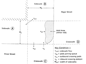
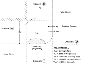
W_a, Walkway Width Left of Sidewalk A
|
Total walkway width of sidewalk on left (used for pedestrian analysis with HCM since 6th Edition).

|
Note: Review HCM 6th Edition Exhibits 19-29 and 19-30. Width is the dimension of the landing area for curb ramps which may differ from the actual paved width of the sidewalk parallel to the approaches.
|
|
ft or m
|
x
|
|
|
|
|
|
|
|
W_b, Walkway Width of Sidewalk B
|
Total walkway width of sidewalk on right (used for pedestrian analysis with HCM since 6th Edition).
|
ft or m
|
x
|
|
|
|
|
|
|
| Radius Corner Curb |
Corner radius (used for pedestrian analysis with HCM since 6th Edition) is visualized in the Network Editor.
|
|
Note: Pre PTV Vistro 2021 networks that had a default 0 value will have a radius of 0 leading to sharp edges when the network is opened in PTV Vistro 2021 or later versions. To change the radius for all intersections at the same time use the Radius Corner Curb attribute in Multi Change tool under Edit > Multi Change.
|
|
ft or m |
|
|
|
|
|
|
x |
|
Crosswalk
|
A checked box defines a crosswalk on the selected approach
|
|
x
|
x
|
x
|
|
|
|
x
|
|
Crosswalk Width
|
Width of the crosswalk visualized in PTV Vistro. This parameter is used if exporting to Vissim. In Vissim the crosswalks are modeled using two opposing links, so each link has half the width of the full crosswalk width. A crosswalk with of 5 ft will generate a 10 ft crosswalk after exporting to Vissim.
Default = 6 ft (1.8 m) Range = 0 – any real number
|
ft or m
|
|
|
|
|
|
|
x
|
| Crosswalk Length |
Defines the length of the crosswalk.
|
ft or m |
|
|
|
|
|
|
x |
|
No. of Right-Turn Channelizing Islands
|
The number of channelized right-turn islands encountered by pedestrians while crossing one intersection leg (used for pedestrian analysis with HCM since 6th Edition).
|
|
x
|
|
|
|
|
|
|
|
Channelized
|
A checked box defines a channelized right turn lane (left turn for left-hand model) for the approach.
|
|
|
|
|
|
|
|
x
|
|
Channelized Control
|
For a channelized turn lane, defines the control for entering the mainline traffic.
Options: SC (Signal Control), Stop, Yield, Target Lane (free)
|
|
|
|
|
|
|
|
x
|
|
Channelized Radius
|
Radius of the channelized turn that tangentially approximates to the outer boundary of the two approaches of the turn movement.
Default = 20 ft. Range = 0 – approach link length
|
ft or m
|
|
|
|
|
|
|
x
|